Robotic deburring is the use of an industrial robot—typically a six-axis articulated arm—fitted with a deburring end effector such as a high-speed spindle, carbide cutter, abrasive brush, or force-controlled grinding head to remove burrs, flash, and sharp edges from cast or machined parts automatically. The goal is a repeatable, specified edge condition, achieved cycle after cycle without manual touch-up.
Behind that definition sit real engineering decisions: which burrs you are fighting, which tool removes them, how the robot finds the edge, and how the system copes with part-to-part variation. This guide covers all of it, from burr fundamentals to cell architecture, applications, and the practical question of when a robot is worth the investment. Two related deep dives: robotic polishing machine selection and robotic grinding for cast parts. For how these cells are configured in practice, see our overview of the robotic deburring process and equipment.
What Is a Burr, and Where Does It Come From?
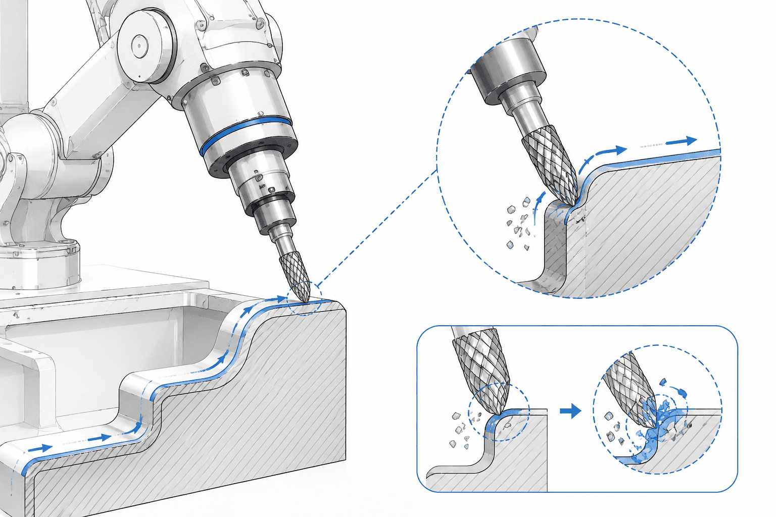
A burr is any unwanted projection of material that extends beyond the intended geometry of a workpiece—usually a thin, rolled, or torn edge created when a cutting tool, die, or mold deforms material instead of cleanly shearing it. Burrs are not material defects; they are the unavoidable byproduct of how parts are made. Every milling pass, drill breakthrough, casting cycle, and cutoff operation leaves some form of edge disturbance.
Four burr families account for most of the edge-finishing workload in automotive and electronics plants:
| Burr type | How it forms | Typical size | Where you see it |
|---|---|---|---|
| Machining burrs | Material rolls or tears at tool exit—drill breakout, milling edge exit, turning cutoff | Typically 0.1–0.5 mm | CNC-machined parts, bored holes, pocket edges |
| Parting-line flash | Molten metal squeezes into the gap between die halves during high-pressure die casting | Roughly 0.1–0.8 mm | Die-cast housings, gear cases, brackets |
| Gate and riser residue | The stub left behind after runners, gates, or risers are removed from a casting | 0.5–2 mm or more | Aluminum and zinc castings prior to machining |
| Oxide scale and forging skin | Oxidized surface layer forms on forgings or heat-treated blanks and cracks into flakes at edges | Varies with process | Forged cranks, arms, hot-formed blanks |
The engineering difficulty is not the size of any single burr—it is the combination of position and variability. A milling burr sits on a predictable edge but varies with tool wear; casting flash runs along a sealed contour but shifts by a few tenths of a millimeter with die wear and shot conditions. A finishing process that cannot tolerate that variation will either leave burrs behind or gouge the part. That constraint, more than anything else, drives the move from manual methods to robotics.
Why Deburring Is Necessary
Burrs are small, but they fail parts in disproportionately expensive ways, for reasons that go well beyond cosmetics:
- Injury risk. Sharp edges cut assembly workers, inspectors, and end users; many automotive OEMs impose measurable edge-radius requirements precisely to control laceration risk.
- Fatigue and fracture initiation. A burr is a stress concentrator. On cyclically loaded parts—suspension components, motor shafts, aerospace structures—a sharp edge becomes a crack initiation site that measurably shortens fatigue life.
- Assembly interference. Burrs on mating faces and locating holes prevent parts from seating correctly, skew dimensional checks, and jam automated feeding and press-fitting operations downstream.
- Sealing integrity. On hydraulic manifolds, valve bodies, and flanged joints, a burr across a sealing surface is a leak path. It can later break loose and score valve spools or clog orifices.
- Coating and surface treatment. Paint, anodize, and plating build up thinly over projections and tear at sharp edges, causing early coating failure or rejected cosmetic parts.
- Downstream tool damage. Loose burrs that break off inside a CNC fixture, engine oil gallery, or brake circuit become FOD with serious warranty consequences.
Edge finishing is also a quietly large cost center. Deburring happens late in the process, on parts that already carry most of their accumulated value, so every scrapped or reworked part at this stage is maximally expensive. Edge finishing is widely estimated to absorb a double-digit share of total part cost in precision machining—hardly a stage to leave to improvisation.
Traditional Deburring Methods and Their Limits
Before robots, plants relied on a handful of established processes, and each still has a legitimate place. The problems appear when part geometry, consistency requirements, or takt times exceed what these methods can hold.
| Method | How it works | Where it falls short |
|---|---|---|
| Manual deburring | Operator works each edge with files, scrapers, deburring knives, or die grinders | Quality varies by operator, hand fatigue, and shift; slow on multi-edge parts; hard to audit; long-term repetitive-strain injury exposure |
| Thermal-energy deburring | Parts are loaded into a sealed chamber; a combustive gas ignition flashes burrs away in milliseconds | High equipment cost; all-over effect cannot spare specific surfaces; risk of heat-affecting thin edges; chamber size limits part size |
| Barrel tumbling | Parts rotate in a drum with abrasive media | Cycle times of hours; media cannot reach internal cavities, deep pockets, or tapped holes; edge radius is difficult to control precisely; part-on-part damage risk |
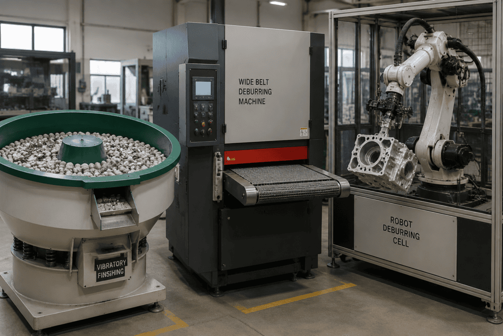
| Vibratory finishing | Parts vibrate with media in a tub or bowl | Same reach limits as tumbling; removes material indiscriminately across all exposed surfaces; unsuitable for large structural parts or critical cosmetic faces |
Two failures matter most for high-mix, high-volume plants. First, bulk processes (tumbling, vibratory) act on every exposed edge at once—both their strength and their blindness: they cannot distinguish a 0.3 mm flash line from a critical sealing chamfer, and they never reach internal features. Second, every method above substitutes operator skill or media dwell time for a defined, part-specific process. When a customer audit asks “what is your burr spec and how do you hold it,” these methods are difficult to defend.
Robotic deburring exists precisely to close that gap: part-specific, edge-specific, data-recordable, and fast enough to match production takt.
How Robotic Deburring Works
Every robotic deburring system answers three questions: where is the edge, what removes it, and how hard does the tool press. The architecture follows from the answers.
Two Cell Layouts
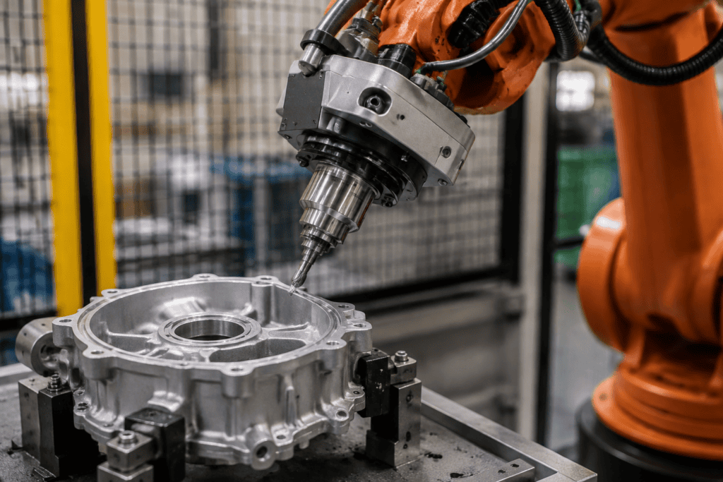
In a tool-in-hand cell, the robot carries the spindle or brush and follows the edge of a fixtured part. This is the most common layout for machined components: one robot services several fixtures or a pallet conveyor, and changing parts means changing the program, not the hardware.
In a part-in-hand cell, the robot grips the workpiece and presents it to a fixed high-speed spindle or brushing station. This layout suits small, high-volume parts where a powerful stationary spindle does the cutting and the robot provides fast, accurate positioning—effectively a flexible alternative to dedicated fixtures. Heavy 6-axis deburring equipment can combine both roles in one line, presenting parts on one side while finishing them on the other.
Four Tooling Approaches
Spindle with carbide or milling cutters. A motorized spindle (commonly in the 10,000–40,000 rpm class) drives carbide burrs, chamfer mills, or dedicated deburring tools. This is the workhorse for coarse stock: gate and riser stubs, thick parting-line flash, and heavy machining burrs. The cutter path and edge geometry are programmable, so chamfer size is controlled directly rather than hoped for.
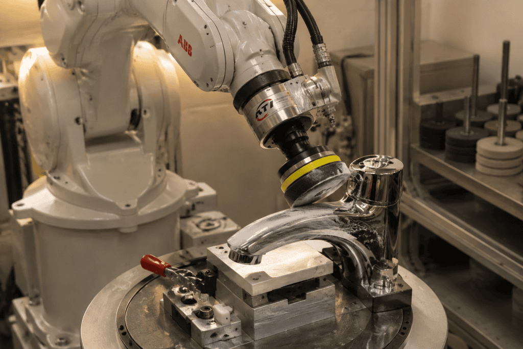
Abrasive brushes. Nylon abrasive brushes, cup brushes, and wire wheels clean up the edge after cutting, blending the chamfer into the surrounding surface and removing secondary feather burrs that cutters create. Brushes are forgiving—their bristles comply with moderate edge variation—which makes them the standard second pass after spindle work. They run at far lower speeds than cutting spindles.
Force-controlled grinding heads. For cast surfaces that vary part to part, pure position control is brittle: program the tool 0.3 mm too close and it gouges; 0.3 mm too far and it misses. Force control solves this. Active heads measure contact force and adjust the robot’s position in real time, holding a programmed normal force—commonly 5–40 N for edge work, and higher for heavy stock removal—so the tool follows the actual surface instead of the nominal model. Passive compliance devices (floating spindles, radial-compliance cartridges) achieve a similar effect mechanically for lighter duty.
Vision and laser localization. Casting flash shifts with die condition, and machined parts land in fixtures with a millimeter or two of placement error. A camera or laser sensor locates key features on each part before cutting, and the system shifts or re-solves the tool paths—within a compensation window on the order of 1–3 mm—to match reality. Without this step, robotic deburring of cast parts degenerates into a scrap generator whenever upstream variation creeps in.
In practice, a serious cell layers these approaches: locate the part, rough the heavy flash with a spindle, finish with a brush or compliant head, all under force or vision supervision. That layering is what separates a demonstration video from a cell that survives Monday morning with a worn die.
Core Components of a Robotic Deburring System
| Component | Function |
|---|---|
| Six-axis industrial robot | Provides reach around complex part geometry; modern arms hold repeatability to hundredths of a millimeter |
| Deburring spindle or tool | Delivers cutting speed and torque matched to the burr type and material |
| End-effector tool changer | Lets one cell swap between spindle, brush, and gauge within a cycle |
| Force-control module | Active (sensor-driven) or passive (mechanical compliance) contact-force regulation |
| Fixturing and part presence sensing | Locates the part repeatably; confirms correct loading before the spindle spins |
| Vision or laser localization | Corrects tool paths for part placement and upstream variation |
| Controller and programming interface | Offline programming, path editing, and process data logging for quality audits |
| Safety enclosure, chip and dust extraction | Protects operators from rotating tooling; removes aluminum dust—a combustible-hazard concern—and coolant residue |
Two integration details deserve more attention than they get. Dust and chip management is not cosmetic: fine aluminum dust is a genuine combustion risk. And process data logging—forces, spindle loads, cycle completion per edge—turns the cell from a machine into a quality record, exactly what PPAP-minded customers ask to see.
Typical Applications of Robotic Deburring
Die-Cast Components
High-pressure die casting guarantees flash: dies wear, parting lines seal imperfectly, and every housing emerges with a flash line plus gate residue. Motor housings, gear cases, and brackets are the classic robotic deburring parts—aluminum, complex perimeter, high volume. Our automated deflashing and deburring solution for die-cast motor housings shows the typical chain: locate the casting, mill the flash and gate stubs, then brush the edges to the specified condition.
Machined Automotive Parts
Machined aluminum components—pumps, valve bodies, calipers, brackets—carry burrs from every milling, drilling, and boring exit. Safety-critical parts add pressure: a robotic grinding and deburring cell for brake calipers must deliver the same edge condition on every casting regardless of incoming variation, because brake hydraulics tolerate no debris. At the engine end of the plant, an aluminum cylinder block robotic deburring and grinding line tackles one of the hardest variants of the problem: burrs deep in oil galleries and water jackets, where manual access is poor and a missed burr becomes circulating engine debris.
3C and Consumer Electronics
Smartphone mid-frames, laptop housings, camera rings, and heat sinks are deburring-intensive because they combine tight cosmetic standards with very high volumes. Small part-in-hand cells dominate here: a robot presents each part to precision spindles and brushes with cycle times measured in a few seconds per feature. Edge quality is the product—visible burrs on an anodized frame are a line reject.
EV and Large Structural Components
EV manufacturing has pushed robotic edge finishing toward parts that barely fit in a cell: battery trays with long weld seams and trimmed flanges, structural castings replacing dozens of stamped pieces, and mixed-material busbar and motor components. Our EV battery tray robotic grinding solutions are representative: large envelopes, long continuous paths, and surfaces that vary with each weld and casting batch—exactly where force-controlled, vision-corrected robotic finishing beats both manual work and fixed automation.
When Is Robotic Deburring Worth It?
A robot is not automatically the right answer; an honest evaluation turns on four factors:
- Volume and part family stability. Robotic cells pay back when they run the same or related part families for years. Plants producing thousands of castings or machined parts per month, or serving medium-volume parts across a stable family with quick-change fixturing, are the natural fit. One-off prototypes and job-shop quantities rarely justify the engineering.
- Edge count and manual cycle time. If an operator needs more than roughly 30–60 seconds per part with a hand tool, and that part repeats all day, the labor arithmetic is already pointing at automation.
- Consistency requirements. When the customer specifies an edge condition—radius range, no burr above a stated height, chamfer tolerance—manual deburring becomes difficult to defend in audits. Robots run the same path at the same force every cycle and can log proof of it.
- Upstream variation. Counterintuitively, casting variation is a reason *for* robotics rather than against it: vision correction and force control handle variation systematically, whereas manual operators absorb it inconsistently.
The cases against robotics are equally clear: very low volumes, parts with burrs at only one or two easily reached edges, workpieces too large for economical handling, or edge requirements so tight (micron-level form) that they belong in the machine tool. Note also that deburring is often bundled with adjacent operations—grinding parting lines, polishing, gauging—because sharing the robot and fixtures across them is what makes the cell economics work.
Robotic Deburring vs. CNC In-Machine Deburring
Because parts pick up machining burrs inside the CNC anyway, a fair question is why not simply finish them there. In-machine deburring—a final milling pass, chamfer cycle, or high-speed spindle in the tool changer—works within its limits, and many plants use both approaches on the same part. For a full map of every machine class that removes burrs, from vibratory bowls to robotic cells, see our deburring machine types guide.
| Dimension | CNC in-machine deburring | Robotic deburring cell |
|---|---|---|
| Precision | Machine-tool accuracy, micron-level control of chamfer geometry | Robot repeatability plus force control; edge geometry held more coarsely but consistently |
| Burr size handled | Small machining burrs, edges reachable by a programmed tool | Heavy flash, gate stubs, grinding-scale stock that a milling cycle cannot address |
| Machine occupancy | Consumes spindle time on your primary asset | Runs offline; CNC is freed for cutting work |
| Part variety | New program per part; fixturing constraints apply | Quick-change fixtures and vision re-targeting handle part families |
| Scope | Confined to the machine envelope and tool reach | Handles casting flash, welds, and finishing beyond what the machining center sees |
The practical division of labor: take the small, geometrically well-defined machining burrs off inside the CNC when the tool can reach them cleanly, and pull the part out for robotic deburring when burrs are large, access is awkward, cycle time is precious, or the operation includes grinding and finishing the CNC was never meant to do. Die-cast parts, which never touched a CNC before finishing, skip the question entirely and go straight to the robotic cell.
Frequently Asked Questions
What is the deburring process?
Deburring is a finishing process that removes burrs—sharp, unwanted projections of material—from the edges and holes of a workpiece after machining, casting, or forming. It is performed manually, with bulk processes such as tumbling and vibratory finishing, thermally, or with dedicated machines, typically followed by cleaning and inspection to verify the edge condition.
Why is deburring necessary?
Deburring protects people and products. Burrs cause cuts during handling and assembly, act as crack initiation points that shorten fatigue life on loaded parts, interfere with assembly fit, and create leak paths across sealing surfaces. They also degrade coatings and can break off as debris inside engines, valves, and hydraulic systems, where the cost of a failure dwarfs the cost of the finishing step.
What is a deburring machine?
A deburring machine is any equipment built to remove burrs in a defined, repeatable way—tumbling barrels, vibratory bowls, thermal deburring chambers, brush machines for flat stock, and robotic deburring cells. The common thread is a controlled process replacing hand work; the choice among them depends on part size, geometry, burr type, and required consistency.
How does robotic deburring work?
A robotic deburring cell uses a six-axis robot carrying a spindle, cutter, or brush (or holding the part against fixed tooling). The robot follows programmed paths along the part’s edges; vision or laser sensors correct for part position, and force control keeps tool pressure constant against surface variation. The result is a repeatable edge condition at production speed, with every cycle logged.
Manual vs. robotic deburring: which is better?
Manual deburring wins on flexibility and low upfront cost for small volumes, simple parts, and development work. Robotic deburring wins on everything that repeats: consistency, speed, labor cost per part, worker safety, and provable process control. Most manufacturers converge on a hybrid: manual finishing for exceptions and oddities, robotic cells for the repeating families that consume most of the labor.
निष्कर्ष
Robotic deburring is not exotic technology reserved for showcase plants—it is the standard answer to a problem every manufacturer shares: burrs that must come off, edges that must be consistent, and volumes manual work cannot serve economically or auditably. Understanding your burr types, part variation, and edge requirements is the real starting point; the robot, spindle, and force-control hardware follow from those facts.
If you are weighing a cell for castings, machined components, or large EV structures, UBright Solutions engineers application-specific robotic deburring and grinding systems around your parts and takt requirements. Send us your part drawings and burr samples, and we will tell you plainly what a cell for them would look like.