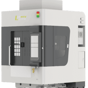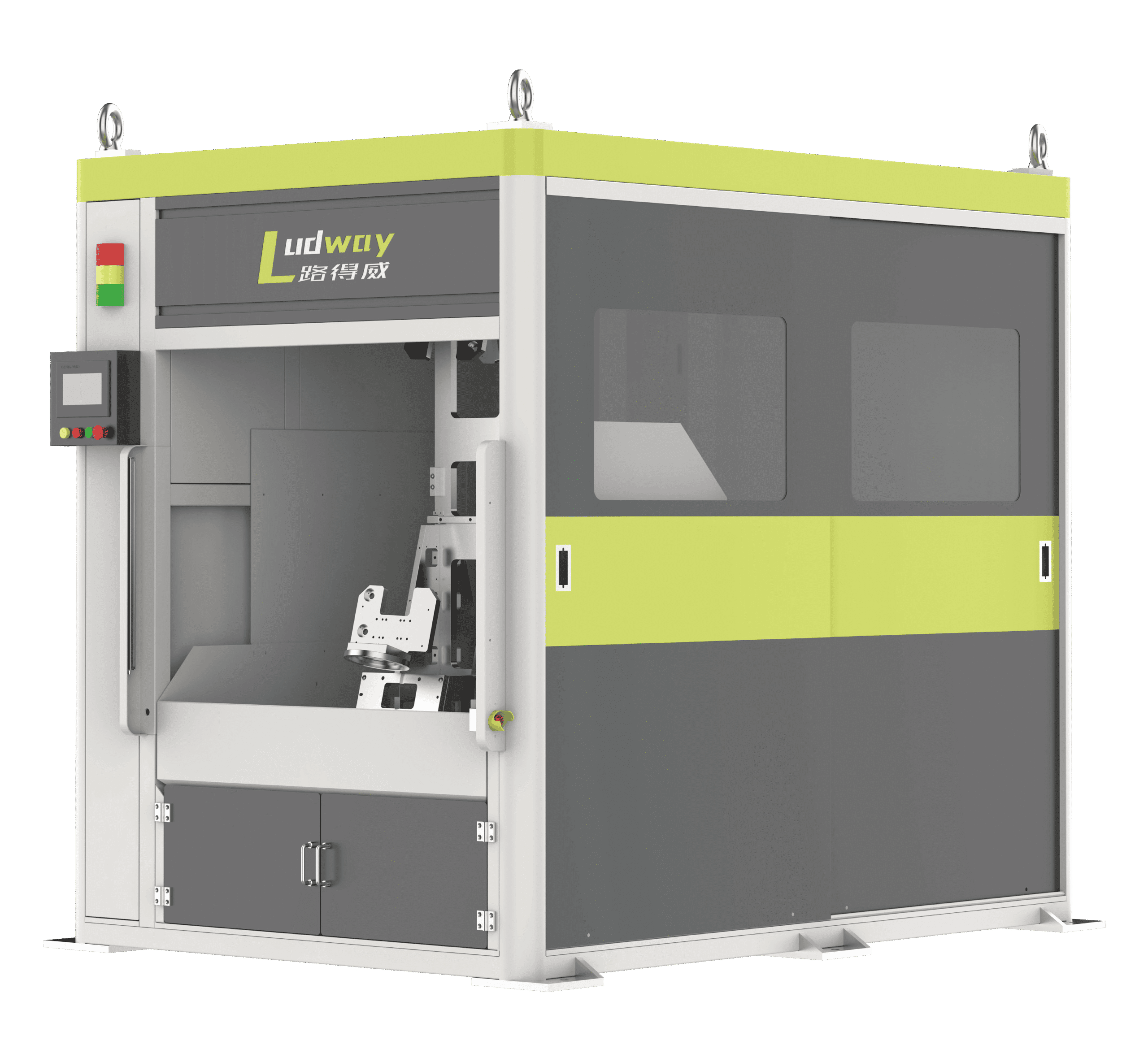
A Robot Cell, Not a Machining Center
The LDW-R7 series answers a different question than the five- and six-axis machines elsewhere in this catalog. Those are machine-tool platforms: a column, a worktable, and travel axes that determine what the machine can reach. Here the working unit is an industrial robot arm carrying a deburring and polishing spindle at its wrist, with a working range of Ø1600 mm. Reach and access come from the arm’s articulation rather than from axis travel, which changes the economics of complex geometry: a part with burrs on five sides, deep pockets, or reversing contours is reached by reorienting the wrist, not by re-fixturing the part.
The trade is precision. The cell holds ±0.05 mm, against ±0.02 mm/300 mm for the machine-tool builds in the same catalog. For the great majority of deburring, edge breaking, and surface finishing work, that is comfortably sufficient, because the tolerances that matter are edge condition and cosmetic quality rather than machined position. Where a print calls for gauge-controlled machined datums, the machine-tool platforms are the better tool, and the selection guide linked below draws that line explicitly.
How the Cell Is Put Together
An R7 cell stacks four elements: the robot arm, the spindle it carries, the fixtures on the workstations, and the guarding and controls around them. The spindle runs from 3000 to 24000 RPM and is offered at 2.2, 3.5, or 5.5 kW, oil-cooled for stability at high speed with low vibration and long bearing life. Tools clamp from Φ3 to Φ13 mm, covering carbide burrs, chamfer mills, mounted points, flap wheels, and brush packs for both deburring and polishing steps on one part.
Control is selectable among Mitsubishi, KND, and Taiwan Xindai, all mature industrial systems, and the choice usually follows a plant’s existing standard, maintenance familiarity, and budget rather than any process difference. A handwheel ships as standard for setup and recovery, and automatic lubrication carries the cell through long production runs. Two mechanical configurations define the range: the LDW-R7-2, a single robot serving two stations, and the LDW-R7-3, the robot clamping tool layout with three stations.
Programs are taught rather than coded: the operator guides the tool along the part once, and the path is stored and recalled by workpiece. Because the arm holds the tool, changing part families usually means changing fixtures and recalling another taught program, not re-engineering the machine.
Specifications of the Two Configurations
| Specifications | LDW-R7-2 | LDW-R7-3 |
|---|---|---|
| Model | LDW-R7-2 | LDW-R7-3 |
| Robot Type | Single Robot Dual Station | Robot Clamping Type |
| Working Range | Ø1600 mm | Ø1600 mm |
| Idle Speed | 35000 mm/min | 35000 mm/min |
| Processing Speed | 1000-10000 mm/min | 1000-10000 mm/min |
| Spindle Cooling Method | Oil Cooling | Oil Cooling |
| Air Pressure Requirement | 0.5 – 0.6 MPa | 0.5 – 0.6 MPa |
| Number of Stations | 2 | 3 |
| Processing Accuracy | ±0.05 mm | ±0.05 mm |
| Total Machine Weight | 3T | 5T |
| Control System Brand | Mitsubishi / KND / Xindai | Mitsubishi / KND / Xindai |
| Handwheel | Standard Equipped | Standard Equipped |
| Lubrication System | Automatic Lubrication Device | Automatic Lubrication Device |
| Spindle Power | 2.2 kW / 3.5 kW / 5.5 kW | 2.2 kW / 3.5 kW / 5.5 kW |
| Spindle Speed Range | 3000 – 24000 RPM | 3000 – 24000 RPM |
| Tool Clamping Range | Φ3 – Φ13 | Φ3 – Φ13 |
Note: all technical specifications are subject to change without prior notice for product optimization and upgrade.
Centralized Deburring Operations
The economics of this machine are designed around labor, not just speed. Cells are fitted with storage bins for raw and finished parts, and the stations keep loading and unloading out of the machining cycle. In practice one operator manages five to ten units, responsible only for handling material, while the robots run their taught programs continuously. That is the pattern that replaces a bench of ten manual deburring stations with a robot row and one person, and it is the reason the R7 fits plants whose pain is staffing and consistency rather than cycle time.
Parts That Suit the Robot Cell
- Workpieces with complex shapes and multi-sided burr locations, where an articulated tool approach beats re-fixturing.
- Castings and components from stable molds at mass-production volumes, which is when high-takt automated deburring pays for itself.
- Parts whose requirements are edge condition and finish quality within ±0.05 mm, rather than machined datum tolerances.
- Families of small to medium parts that fit within the Ø1600 mm working envelope and finish with tools up to Φ13 mm.
Where a part needs tighter precision or heavier milling stock removal, the machine types guide explains when the five-axis and six-axis platforms take over.
Background Reading
Two guides frame the decision this page sits in. What Is Robotic Deburring? covers the process itself, tool selection, force and speed considerations, and what moving from manual benches to a robot cell changes on the shop floor. The Types of Deburring Machines: Complete Selection Guide compares robot-held-tool cells against machine-tool-style equipment across precision, geometry, and volume, which is precisely the comparison an R7 buyer is making.
Discuss Your Application
Send part drawings, burr locations, and volumes through the contact page. UBright will confirm the configuration, two stations or three, spindle power, and control brand, propose the tool plan inside the Φ3 to Φ13 mm range, and demonstrate the taught process on sample parts before you commit to the cell.