In the 3C consumer electronics sector, the cosmetic texture of a smartphone is the core element dictating consumer purchase intent. As top-tier flagship models completely transition from aluminum to ultra-hard stainless steel and Titanium, the mirror polishing and micro-hole deburring of the mid-frame have become the ultimate nightmare for OEMs and EMS providers. This article explores how, amidst high-volume production, utilizing highly agile industrial robots holding workpieces against heavy-duty floor-mounted polishing centers—integrated with advanced automated systems—can completely eradicate industry pain points like titanium orange peel and melted antennas, delivering flawless, jewelry-grade results consistently.
What is a Smartphone Metal Mid-Frame?
The smartphone mid-frame (or chassis) is the skeleton of the device. It supports the screen, back cover, and motherboard, and crucially, it is the primary cosmetic component that users physically touch and visually focus on.
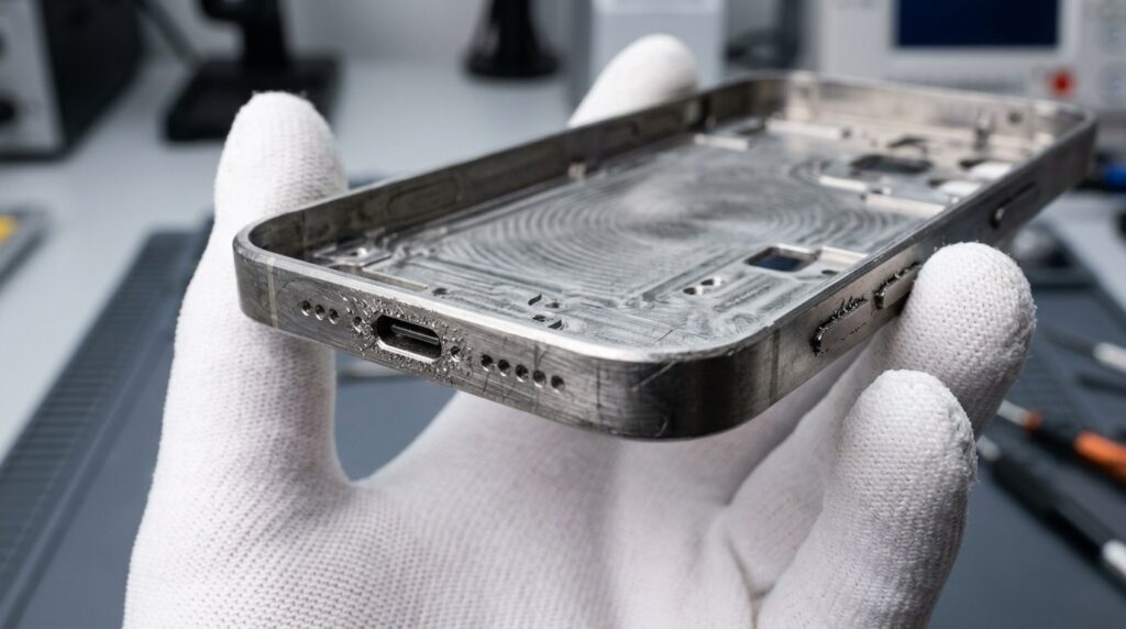
Smartphone Mid- Frame Polishing Scenarios
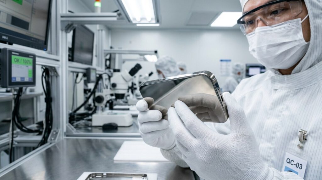
To achieve the ultimate tactile and visual luxury, mid-frames of top flagship phones (like the latest Pro series) are typically forged from titanium alloys or high-hardness medical-grade stainless steel, undergoing dozens of ultra-precise CNC milling steps.
Straight off the CNC machine, the frame is covered in microscopic milling tool marks. Furthermore, incredibly sharp micro-burrs are left around the tiny volume button holes, USB-C ports, and speaker arrays. If not subjected to extreme surface blending and polishing, this leads directly to poor adhesion and color variance in subsequent PVD coatings, and can even cut the user’s fingers.
Smartphone Mid- Frame Structural Characteristics
Surface treatment of these frames faces draconian physical challenges:
- Exceedingly Fragile Micro-Holes: Frame edges are riddled with holes merely 1-2 mm wide. Too much polishing force instantly deforms the holes or collapses their edges.
- Seamless Joining of Dissimilar Materials: Metal frames embed plastic/resin antenna bands. Immense friction heat during polishing easily melts the plastic or creates a sharp “step difference” at the metal-plastic boundary.
- Extreme Stickiness and Heat Sensitivity of Titanium: Titanium conducts heat poorly. Traditional polishing causes the surface to heat up violently, producing highly visible “Orange Peel” rippling and thermal discoloration.
Key Characteristics of Smartphone Frame Polishing
الخصائص الرئيسية:
- Absolute Gloss/Matte Consistency: Whether requiring a flawless mirror reflection or a fine brushed matte, across tens of millions of units, the 1st and the 10,000,000th smartphone frame must look 100% identical.
- Zero Edge Rounding: Polishing must never destroy the sharp right-angle edges milled by the CNC or violate strict screen assembly tolerances.
- Extreme Cycle Times and Yield: Smartphones have short lifecycles. Contract manufacturers must compress the frame’s cycle time to the limit while maintaining yield rates above 99.5%.
Technical Parameters for Phone Frame Polishing
| البند | نطاق المعلمات | الملاحظات |
| Micro-Hole Deburring | Custom Micro SiC Nylon Brush | Sweeps 1mm holes without altering diameter |
| Titanium Flattening | High-Density Sisal / Composite | Uses cooling cut wax to erase CNC steps |
| Mirror Deep Polish | Soft Cotton + High-Gloss Wax | Awakens deep, clear liquid metal luster |
| التحكم في قوة الاتصال | 5N – 15N (High-Freq Adaptive) | Protects plastic antennas, prevents deformation |
| وقت الدورة | 60s – 90s / Piece | Ultra-fast output within a single enclosed cell |
Why Must Premium Frames Use the “Robot-Holding-Workpiece” Architecture?
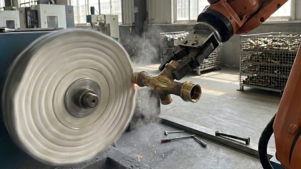
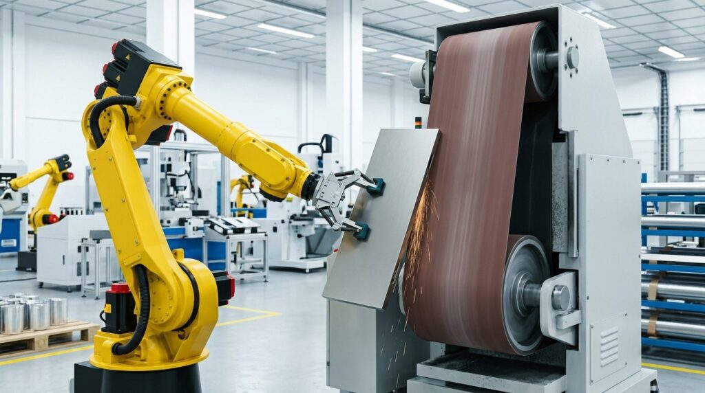
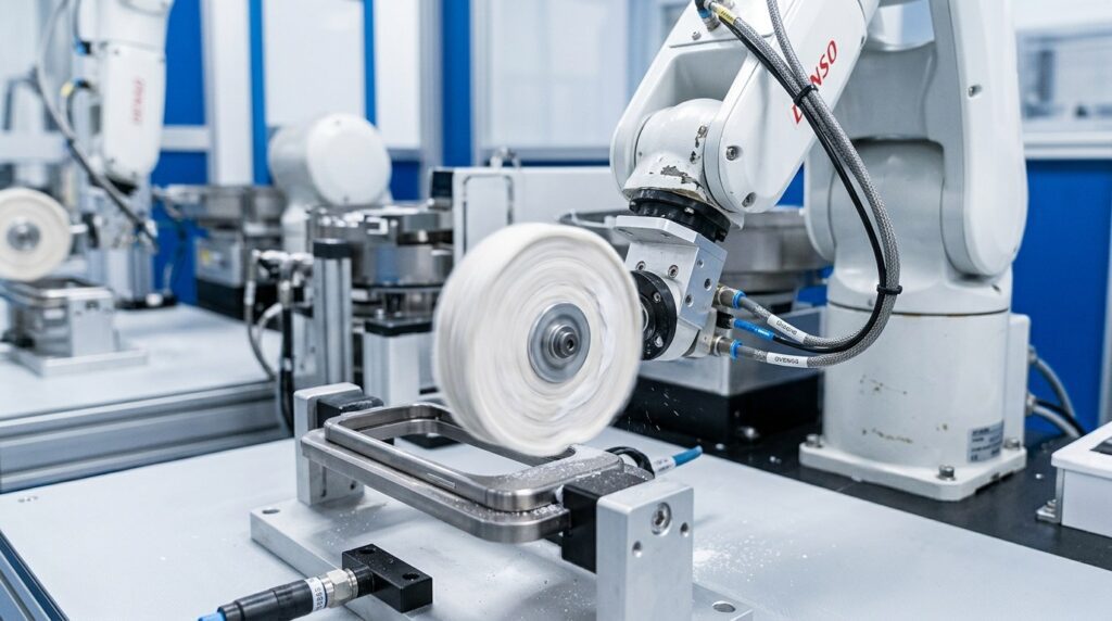
When processing small yet highly complex 3C structural components, the industry standard is for a 6-axis industrial robot on the left to securely grip the mid-frame (Workpiece) and precisely maneuver it against heavy-duty, multi-station polishing machines (Tool) mounted securely to the floor on the right.
Flaws of Manual or Simple Dedicated Machines
| نقطة الألم | مشكلة محددة | التأثير |
| Disastrous Antenna Step Differences | Manual force is uneven; softer plastic antennas are instantly gouged out. | Creates a cutting feel; premium units are scrapped. |
| Titanium Orange Peel | Polishing wheel temperature spirals, titanium rapidly builds local heat. | Creates irreversible orange peel, ruining PVD coatings. |
| Wild Capacity & Yield Fluctuations | Relies entirely on the stamina of hundreds of workers. | Yields fluctuate violently (80%-90%), devouring margins. |
The Overwhelming Advantage of Heavy-Duty Robotic Cells
| Comparison | Traditional Grinding | Robot Gripping Part + Force Control | التحسينات |
| Complex Curvature | Rigid, leaves dead zones | Robot flips and twists the part against the belt | Perfect, dead-zone-free transitions on sides and R-corners |
| Dissimilar Materials | Causes steps | Milli-Newton force response yields instantly on plastic | Flawless, seamless flushness between titanium and antenna |
| Heat Control | Causes orange peel | Rapid robot sweeping + auto wax spray cooling | Eradicates orange peel, leaving a jewelry-grade mirror |
| Agile Changeover | Requires new jigs | OLP one-click phone model changeover | Perfectly adapts to the brutal 6-month 3C iteration cycle |
The Core Advantage: Active Force Control.
As the robot grips the phone frame and presses its edge against the fiercely spinning floor-mounted buffing wheel on the right, the force sensor detects the resistance shift from “hard titanium” to “soft antenna band” in milliseconds. The robot instantly and automatically reduces contact pressure, gliding over the plastic before restoring pressure. This “smart floating contact” ensures the incredibly delicate phone frame maintains perfect dimensional accuracy even under the friction of heavy machinery.
Automated Smartphone Frame Polishing Process Workflow
Inside a fully enclosed industrial cell, the robot collaborates with the heavy-duty floor-mounted polishing center on the right to complete 8 extremely compact steps.
Smartphone Mid-Frame Robotic Polishing & Deburring Process Flow
| الخطوة | اسم العملية | Equipment Layout | الوقت | الدقة/الغرض |
| 01 | التحميل الموجه بالرؤية | Robot grabs part from tray using vision | 5s | Rapid precise grip, ensuring correct trajectory origin |
| 02 | Micro-Hole Deburring | Robot presses part to fixed micro brush | 15s | Softly sweeps micro-flash from USB & button holes |
| 03 | Edge Rough Flattening | Robot moves to large floor sisal station | 25s | Cuts CNC marks, levels metal/plastic antenna seams |
| 04 | Titanium Blending | Robot moves to soft composite wheel | 20s | Refines scratches, strictly controls temp with cold wax |
| 05 | Edge Mirror Polish | Robot moves to soft cotton wheel | 25s | High-speed buffing awakens clear, deep mirror gloss |
| 06 | In-line High-Pressure Dewax | Robot moves part to steam nozzles | 10s | Instantly blasts off soft wax before it congeals in holes |
| 07 | Deep Ultrasonic Wash | Multi-tank line at the back of the factory | 120s | Achieves extreme surface cleanliness required for PVD |
| 08 | Automated Optical Insp. | AOI vision tunnel camera comparison | 15s | Auto-rejects any scratch, pit, or orange peel >10 microns |
دراسة حالة
خلفية العميل
A global Top 3 smartphone structural components contract manufacturer (Tier 1 EMS) located in South China. Supplying titanium mid-frames for the latest flagship models of the #1 smartphone brand in North America.
التحديات التقنية
- The client secured massive orders for the newest titanium flagship. However, legacy polishing lines suffered an 18% scrap rate processing titanium, primarily due to sunken antenna bands and severe orange peel.
- The client needed to deliver a staggering 150,000 perfect frames daily under an extreme deadline.
الحل
We deployed an automated array of 100 fully enclosed robotic cells. Inside each cell, a large yellow 6-axis robot on the left gripped the phone frame, processing it against heavy-duty floor-mounted polishing machines on the right. The system deeply integrated milli-Newton active force control and MQL wax cooling. The full polishing cycle time per piece was merely 75 seconds.
نتائج التنفيذ
- Yield Reigns Supreme: With this layout and force control, the antenna step difference was strictly kept under 0.02mm, and orange peel vanished. The overall polishing yield stabilized at a terrifying 99.7%.
- Capacity Explosion: The matrix of 100 robots ran 24/7, stably outputting over 110,000 perfect frames daily, unblocking the capacity lifeline.
- Saving Margins: Drastically reduced reliance on skilled manual polishers, recovering tens of millions in annual titanium scrap losses.
الأسئلة الشائعة
Q1: Will pressing the frame against a heavy-duty polishing machine round off the precise sharp edges?
A: Absolutely not. This is exactly why we use Active Force Control and Offline Programming (OLP). The robot holds the frame at a highly precise tilt angle, allowing the edge to gently “lick” the cloth wheel while maintaining a constant, extremely light pressure via the force sensor. This “Zero Edge Rounding” technique perfectly preserves the sharp lines cut by the CNC.
Q2: How do you prevent polishing wax from clogging the tiny speaker holes?
A: Inside the cell, immediately after the final cloth buffing step (and before the wax can cool and congeal), the robot moves the frame to an adjacent high-pressure, high-temp steam nozzle station. This instantly blasts the residual wax out of the micro-holes, ensuring they are 100% unobstructed.
Q3: Is it difficult to change phone models with this system comprising a robot and heavy floor-mounted machines?
A: It is extremely agile. Based on advanced OLP software, engineers simply import the 3D CAD model of the new phone casing. The software automatically plans the robot’s gripping posture and its trajectory against the polishing machine on the right. Pushing the new program to the cell typically compresses changeover and debugging to under 15 minutes.
الخاتمة
In the fiercely competitive manufacturing ecosystem of 3C consumer electronics, the flawless surface treatment of titanium and stainless steel frames is the critical battle deciding an EMS provider’s survival. Adopting an automated architecture featuring a heavy-duty 6-axis robot holding the workpiece against a massive floor-mounted polishing center, augmented by micron-level active force control, completely ends step defects, orange peel, and yield crashes caused by manual polishing. It outputs tens of millions of jewelry-grade mirror frames with tireless, blazing-fast cycle times.
If you are bogged down by low yields in 3C frame polishing, facing brand rejections due to antenna step differences, or struggling with severe labor shortages, contact our automation expert team immediately to secure your dedicated high-volume polishing technical assessment.