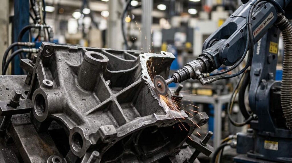
Aluminum alloy bearing ladder frames are structural casting components used in automotive engine lower-frame and crankshaft support systems. Based on the sample workpiece, this part has a ladder-like frame layout, multiple rectangular openings, cross beams, bearing support features, bolt holes, raised bosses and reinforced rib transitions, making post-casting deburring and local grinding more complex than on simple aluminum castings.
This robotic deburring and grinding solution is designed for aluminum alloy bearing ladder frames with typical dimensions around 400–650 mm in length, depending on the engine platform. It helps remove burrs, flash, parting line residues, gate-cut marks and sharp edges from frame rails, bearing support edges, rectangular windows, bolt holes, cross-beam transitions and local rib areas while improving finishing consistency and reducing manual grinding workload.
What Is an Aluminum Alloy Bearing Ladder Frame?
An aluminum alloy bearing ladder frame is a cast structural component used in the lower section of an engine assembly. It usually supports crankshaft-bearing-related areas, reinforces the lower engine structure and connects with the cylinder block, oil pan or other powertrain components through precise mounting and sealing interfaces.
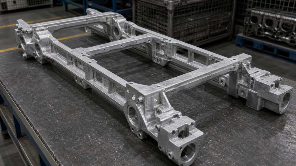
Based on the sample image, this workpiece has a typical ladder-type structure with long side rails, cross beams, rectangular window openings, multiple circular holes, raised bosses and bearing support zones. After casting and trimming, burrs, flash, sharp edges and local gate residues may remain around the windows, rail edges, bolt holes, cross-beam intersections and boss boundaries. For this type of workpiece, the main finishing requirement is robotic deburring, controlled local grinding and edge cleanup rather than decorative polishing.
| البند | التفاصيل |
|---|---|
| اسم قطعة العمل | Aluminum Alloy Bearing Ladder Frame |
| الاسم الصيني | 铝合金轴承梯形框架 |
| الحجم المعتاد | Around 400–650 × 250–400 × 80–180 mm, depending on model |
| المواد | صب سبائك الألومنيوم |
| العملية الرئيسية | إزالة الحواف الخشنة والطحن الآلي |
| العمليات المدعومة | تدوير الحواف، إزالة البروزات، تنظيف السطح الموضعي |
| مجالات المعالجة الرئيسية | Long frame rails, rectangular window edges, cross beams, bearing support edges, bolt holes, boss boundaries, rib transitions, gate-cut areas |
| المناطق المحمية | Bearing support surfaces, mounting faces, sealing rails, precision holes, machined fitting interfaces |
| الهدف النهائي | Remove burrs, flash, sharp edges and local residues while protecting bearing-related and sealing surfaces |
Typical Finishing Challenges of Aluminum Alloy Bearing Ladder Frame
An aluminum alloy bearing ladder frame is difficult to finish because it combines structural strength areas and precision-related interfaces in one casting. The long frame rails and cross beams create many internal and external edges, while rectangular windows and bolt holes generate repeated burr locations across the part.
Manual processing is unstable because operators must switch between long rail deburring, window edge cleanup, hole edge treatment and local grinding around bosses. The bearing support areas and sealing rails must be protected carefully, so excessive grinding force or incorrect tool angle may create tool marks, local over-removal or damage near functional interfaces.
| مشكلة شائعة | مجال محدد | التأثير |
|---|---|---|
| الوميض الناتج عن الصب / خطوط الفصل | Long frame rails, outer perimeter, cross-beam edges | Affects edge consistency and assembly preparation |
| بقايا البوابات | Local gate-cut sections around frame body or rail ends | يتطلب إزالة كمية أكبر من المادة المحلية |
| حواف حادة | Rectangular windows, bolt holes, cross-beam openings | ينطوي على مخاطر تتعلق بالمناولة والتجميع |
| النتوءات المتبقية | Rib roots, boss boundaries, rail intersections | يؤدي إلى عدم استقرار جودة التشطيب |
| التغيير اليدوي | Repeated window edges and hole groups | يؤدي إلى تباين النتائج بين المشغلين |
| المجالات الوظيفية الحساسة | Bearing support surfaces, sealing rails, mounting faces, precision holes | خطر حدوث تلف أثناء الطحن اليدوي |
Robotic Deburring and Grinding Process for Aluminum Alloy Bearing Ladder Frame
A robotic deburring and grinding cell for aluminum alloy bearing ladder frames should be designed around frame rigidity, tool reach, force control and protected-zone management. The process must remove burrs and flash from rails, windows, holes and cross beams while avoiding contact with bearing support surfaces, sealing rails and machined interfaces.
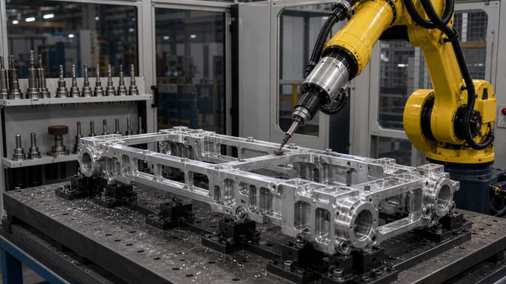
For bearing ladder frames with typical dimensions around 400–650 mm in length, the process usually includes loading, program selection, protected-area confirmation, rail contour grinding, window edge deburring, bearing support edge cleanup, rib transition finishing, inspection and unloading. Different tools can be used according to defect type, including flexible deburring tools, abrasive grinding tools, chamfering tools and small grinding heads.
| الخطوة | العملية | الغرض | الأداة / النظام |
|---|---|---|---|
| 1 | التحميل والتثبيت | Secure the ladder frame for stable processing | تركيبات مخصصة |
| 2 | اختيار البرنامج | Match the correct frame model and path | واجهة المستخدم / برنامج الروبوت |
| 3 | تأكيد المنطقة المحمية | Define bearing, sealing and mounting no-grind zones | منطق الجدول / إعدادات البرنامج |
| 4 | Frame Rail and Outer Contour Grinding | Remove flash and parting line residues from long rails | أداة طحن كاشطة |
| 5 | Rectangular Window Edge Deburring | Remove burrs from internal frame openings | أداة مرنة لإزالة الحواف الخشنة |
| 6 | Bearing Support and Boss Edge Treatment | Process local edges around bearing support and bosses | أداة تشطيب الحواف / عمود إزالة الحواف الخشنة |
| 7 | Cross-Beam and Rib Transition Finishing | Clean burrs from beam intersections and rib roots | رأس طحن صغير / أداة متوافقة |
| 8 | Gate Residue Local Grinding | Remove thicker local casting residues | Stock-removal grinding tool |
| 9 | فحص الجودة | Check burr removal and protected functional areas | الفحص اليدوي أو البصري |
| 10 | التفريغ والتنظيف | Remove aluminum particles and transfer the part | التنظيف بالهواء المضغوط / التنظيف بالمكنسة الكهربائية |
الخطوة 1: التحميل والتثبيت
The aluminum alloy bearing ladder frame is loaded into a dedicated fixture that supports the casting from stable non-functional areas. Because the workpiece has long rails, cross beams and multiple openings, fixture rigidity is important to prevent vibration during deburring and grinding.
The fixture should keep the bearing ladder frame in a repeatable position while allowing access to outer rails, window edges, bolt holes and beam transitions. Proper positioning also helps the robot maintain a safe distance from bearing support surfaces and sealing interfaces.
الخطوة 2: اختيار البرنامج
After the workpiece is clamped, the operator selects the corresponding robot program through the HMI. This is useful when one robotic cell handles similar ladder frame models with different window layouts, bolt patterns or bearing support structures.
The selected program defines the processing sequence, robot posture, tool type, feed rate, contact force and protected zones. Saved programs make repeated batches more stable and reduce dependence on manual operator judgment.
الخطوة 3: تأكيد المنطقة المحمية
Before grinding starts, the system confirms the no-grind zones. For a bearing ladder frame, protected areas usually include bearing support surfaces, sealing rails, mounting faces, machined pads, precision holes and fitting interfaces.
This step is more important on bearing ladder frames than on general aluminum castings because burr-prone edges may be close to precision-related structures. The robot should remove burrs from the edge boundary while keeping abrasive tools away from functional bearing and sealing surfaces.
Step 4: Frame Rail and Outer Contour Grinding
The robot processes the long side rails and outer contour where casting flash, trimming marks and parting line residues commonly appear. These areas often run along the length of the frame and may include straight segments, corner transitions and local protrusions.
An abrasive grinding tool can follow the programmed rail contour and remove raised defects. For aluminum alloy castings, the grinding depth and contact pressure should be controlled to avoid surface smearing, deep tool marks or unnecessary material removal.
Step 5: Rectangular Window Edge Deburring
The rectangular openings are key processing areas on a bearing ladder frame. Burrs and sharp edges can remain along the window perimeter, especially around corners and cross-beam intersections.
A flexible deburring tool is suitable for window edge treatment because it can follow the internal edge profile while adapting to minor casting variation. The robot should process each window with a stable approach angle to achieve consistent edge rounding without changing the window geometry.
Step 6: Bearing Support and Boss Edge Treatment
Bearing-related support features and raised bosses may have small edge burrs around holes, circular boundaries and local transitions. These burrs must be removed, but the nearby functional surfaces must remain protected.
A chamfering tool, deburring spindle or small abrasive tool can be used for controlled local treatment. The robot processes the edge boundary around each boss or support feature while excluding bearing faces and precision interfaces from the tool path.
Step 7: Cross-Beam and Rib Transition Finishing
The cross beams and reinforced ribs create many intersections where burrs can remain after casting. These areas are often difficult to reach manually because tool angle changes frequently between rails, beams and internal corners.
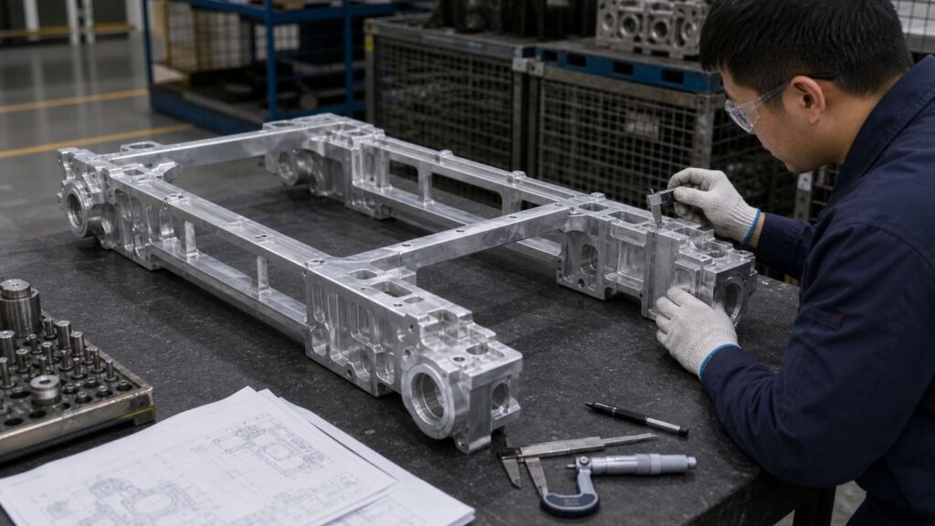
A small grinding head or compliant deburring tool can process rib roots, beam intersections and recessed transitions. The robot can divide the ladder frame into several local zones and finish each transition with repeatable posture.
Step 8: Gate Residue Local Grinding
Some gate-cut areas may contain thicker material than ordinary burrs or flash. These areas require local grinding rather than light edge deburring.
The robot can use a dedicated stock-removal tool with controlled feed speed and pressure. Separating gate residue removal from general deburring prevents unnecessary grinding on clean frame rails and protected functional areas.
الخطوة 9: فحص الجودة
After robotic processing, operators inspect the long rails, rectangular windows, bolt holes, bearing support edges, boss boundaries, rib transitions and gate-cut areas. The inspection confirms that burrs and sharp edges have been removed and that protected surfaces remain undamaged.
Visual inspection can be combined with manual touch checks, sample gauge checks or camera-based inspection depending on production requirements. Inspection feedback can also help optimize path compensation and tool replacement intervals.
الخطوة 10: التفريغ والتنظيف
After inspection, the bearing ladder frame is unloaded and transferred to the next process. Aluminum chips, fine dust and residual particles should be removed from windows, holes and rib intersections.
An enclosed robotic cell with aluminum dust and chip collection is recommended. It helps create a cleaner finishing environment and reduces the operator’s direct exposure to repetitive deburring and grinding work.
صعوبات التصنيع وحلولها
| التحدي | السبب | الحلول الروبوتية |
|---|---|---|
| Long Rail Flash | Frame rails create long parting line and trimming areas | Programmed rail contour grinding path |
| Rectangular Window Burrs | Internal openings create repeated sharp edge boundaries | إزالة الحواف الخشنة بطريقة مرنة على مقاطع النوافذ |
| Bearing Area Protection | Bearing support and sealing surfaces must not be touched | No-grind zones and controlled local paths |
| Cross-Beam Intersections | Beam and rib intersections create narrow burr locations | Small tool access with local finishing routines |
| إزالة بقايا البوابة | Gate-cut zones contain thicker residual stock | Dedicated local grinding path |
| Aluminum Surface Sensitivity | Aluminum alloy can be marked by excessive pressure | Controlled force, suitable abrasive tool and compliance |
Difficulty 1: Long Rail Flash and Parting Line Control
The bearing ladder frame has long side rails and outer contours where flash and parting line residues may appear continuously. Manual grinding along these long edges can create inconsistent edge shape and uneven surface marks.
The solution is to use a programmed rail contour grinding path. This allows the robot to follow the rail geometry with consistent tool contact while removing raised casting defects from repeated edge areas.
Difficulty 2: Rectangular Window Edge Burrs
The multiple rectangular windows create long internal edge boundaries and corner transitions. Burrs can remain along both straight window edges and internal corners, making manual deburring time-consuming and unstable.
The solution is to use flexible robotic deburring along each window profile. The robot can approach the edge with controlled pressure and repeat the same path for each opening, improving consistency across the entire ladder frame.
Difficulty 3: Bearing Support Edge Protection
Bearing ladder frames often include surfaces and interfaces related to crankshaft support or lower engine assembly. These functional zones must not be damaged during grinding.
The solution is to define bearing support surfaces, sealing rails and precision interfaces as protected zones. The robot removes burrs from adjacent edges but keeps the tool path outside critical areas.
Difficulty 4: Cross-Beam and Rib Transition Burrs
Cross beams and ribs improve structural stiffness, but they also create narrow intersections and recessed areas where burrs can remain. These areas are difficult to clean by hand without changing tool angle repeatedly.
The solution is to use a small grinding head or compliant deburring tool. The robot divides the beam and rib structure into local finishing areas and processes each transition with stable posture.
Difficulty 5: Local Gate Residue Removal
Gate-cut areas can contain thicker residual stock than normal burrs. If these areas are processed with only a light deburring tool, residue may remain; if they are over-ground manually, nearby surfaces may be damaged.
The solution is to use a dedicated local grinding routine for gate residues. The robot applies the correct tool, feed rate and contact force only to the affected area, keeping surrounding surfaces protected.
حالة التصنيع
خلفية العميل
An automotive aluminum casting manufacturer produces bearing ladder frames for engine lower-frame and crankshaft support applications. Before automation, operators manually removed burrs, flash, gate residues and sharp edges from long rails, rectangular windows, bolt holes, bosses and cross-beam transitions.
As production volume increased, manual deburring and grinding became difficult to standardize. Window edges and rib transitions were sometimes under-processed, while exposed rail edges could be over-ground by different operators. The customer wanted to improve finishing consistency, reduce manual workload and better protect bearing-related interfaces.
التحديات التقنية
The workpiece had long frame rails, multiple rectangular openings, cross beams, reinforced ribs, hole groups and bearing support features. Burrs appeared across both long external edges and internal window edges, requiring different tool paths and tool angles.
The main technical challenge was balancing material removal and surface protection. Gate-cut areas required stronger local grinding, while bearing support surfaces, sealing rails and precision holes needed to remain untouched.
الحل
The proposed solution used a six-axis industrial robot, a dedicated ladder frame support fixture and a multi-tool finishing system. The robot used an abrasive grinding tool for long rail flash, a flexible deburring tool for window edges, a chamfering tool for bolt holes and bosses, and a small grinding head for beam intersections and rib roots.
Protected bearing support surfaces, sealing rails and machined interfaces were defined in the robot program. The fixture held the workpiece securely while allowing the robot to access both external and internal edges. An enclosed cell with aluminum dust collection was used to control chips and fine particles.
| البند | التكوين |
|---|---|
| قطعة العمل | Aluminum Alloy Bearing Ladder Frame |
| الاسم الصيني | 铝合金轴承梯形框架 |
| الحجم المعتاد | Around 400–650 × 250–400 × 80–180 mm, depending on model |
| العملية الرئيسية | إزالة الحواف الخشنة والطحن الآلي |
| العملية المدعومة | تدوير الحواف، إزالة البروزات، تنظيف السطح الموضعي |
| الروبوت | روبوت صناعي سداسي المحاور |
| الأدوات | Abrasive grinding tool, flexible deburring tool, chamfering tool, small grinding head, stock-removal tool |
| جدول المباريات | Dedicated Bearing Ladder Frame Support Fixture |
| استراتيجية الحماية | Protected bearing support surfaces, sealing rails, mounting faces and precision holes |
| التحكم في الغبار | Enclosed Cell with Aluminum Dust and Chip Collection |
نتائج التنفيذ
The robotic cell took over repetitive deburring and grinding work on long frame rails, rectangular windows, bolt holes, boss edges, beam intersections and gate-cut areas. Operators mainly handled loading, unloading, inspection and tool maintenance, which reduced direct manual grinding intensity and made repeated batches more stable.
The enclosed workstation also improved chip and dust control during aluminum casting finishing. Instead of open manual grinding around the workpiece, aluminum particles were collected inside the cell, helping create a cleaner and more controlled production area.
| مجال النتائج | التحسينات |
|---|---|
| Rail Edge Quality | More stable cleanup along long frame rails |
| إزالة الحواف الخشنة من حواف النوافذ | Better consistency around rectangular openings |
| Bearing Area Protection | Lower risk of damage to bearing support and sealing surfaces |
| Hole and Boss Treatment | Repeatable edge cleanup around holes and raised bosses |
| تشطيب انتقال الأضلاع | Reduced missed burrs at beam and rib intersections |
| Gate Residue Cleanup | Dedicated local paths for thicker casting residues |
| تقليل العمالة | تقليل عبء العمل المتكرر المرتبط بإزالة الحواف الخشنة والتجليخ يدويًّا |
| استقرار الإنتاج | Saved programs for repeated ladder frame batches |
| بيئة ورشة العمل | منطقة تشطيب أنظف مزودة بنظام مغلق لجمع الغبار مصنوع من الألومنيوم |
آراء العملاء
The customer reported that the robotic deburring and grinding cell made repeated bearing ladder frame finishing more stable and reduced the manual effort required for rail cleanup, window edge deburring and local gate residue removal. Operators could focus more on part handling, inspection and tool monitoring instead of continuous manual grinding.
المعلومات المطلوبة لإعداد عرض أسعار خاص بالطحن الآلي
To recommend a suitable robotic deburring and grinding cell for your aluminum alloy bearing ladder frame, we usually need the part drawing, material grade, casting weight, photos of burrs, flash, parting lines or gate residues, required processing areas, protected bearing or sealing surfaces, current manual grinding cycle time and annual production volume.
These details help our engineering team evaluate fixture design, robot reach, tool selection, dust collection layout and process feasibility. For bearing ladder frame castings, it is especially important to identify which areas require material removal and which bearing support, sealing or precision interfaces must be protected during robotic finishing.
الأسئلة الشائعة
Q1: Is this workpiece a bearing ladder frame?
Yes. Based on the sample structure, this workpiece can be described as an aluminum alloy bearing ladder frame. It has long frame rails, cross beams, rectangular window openings, bolt holes, bosses and bearing-related support areas.
Q2: Why is robotic deburring and grinding suitable for this workpiece?
Robotic deburring and grinding are suitable because the part has repeated rails, windows, holes and beam intersections. A robot can follow programmed paths with stable tool contact, improving consistency compared with manual operation.
Q3: What areas can the robot process on a bearing ladder frame?
The robot can process long frame rails, rectangular window edges, bolt holes, boss boundaries, rib roots, cross-beam intersections, gate-cut areas and parting line positions. The exact areas should be confirmed according to the drawing and actual burr distribution.
Q4: Does this aluminum alloy ladder frame require polishing?
In most cases, this part does not require decorative polishing. The main requirement is deburring, local grinding, flash removal and edge rounding. The purpose is to remove burrs and sharp edges while protecting functional surfaces.
Q5: How are bearing support and sealing surfaces protected?
Protected surfaces are controlled through fixture positioning, robot path planning and no-grind zones in the program. Bearing support surfaces, sealing rails, precision holes and machined interfaces are excluded from grinding paths.
Q6: Can one robotic cell handle similar ladder frame models?
Yes. One robotic cell can often handle similar aluminum alloy bearing ladder frame models if the fixture, robot reach and tooling are designed for part variation. Different robot programs can be saved for different part numbers.
الخاتمة
Aluminum alloy bearing ladder frames have long rails, rectangular openings, cross beams, bearing support features, holes and reinforced transitions, making manual deburring and grinding difficult to standardize. A robotic deburring and grinding solution helps manufacturers remove burrs, flash, gate residues and sharp edges while improving consistency and protecting bearing-related functional areas.
If your bearing ladder frame production still relies on manual rail grinding, window edge deburring or gate residue cleanup, اتصل بنا للحصول على حل روبوتي مخصص. يمكنك أيضًا استكشاف السيارات والمركبات الكهربائية التطبيقات و المعدات لمعرفة المزيد عن أنظمة التشطيب الآلية التي نقدمها.