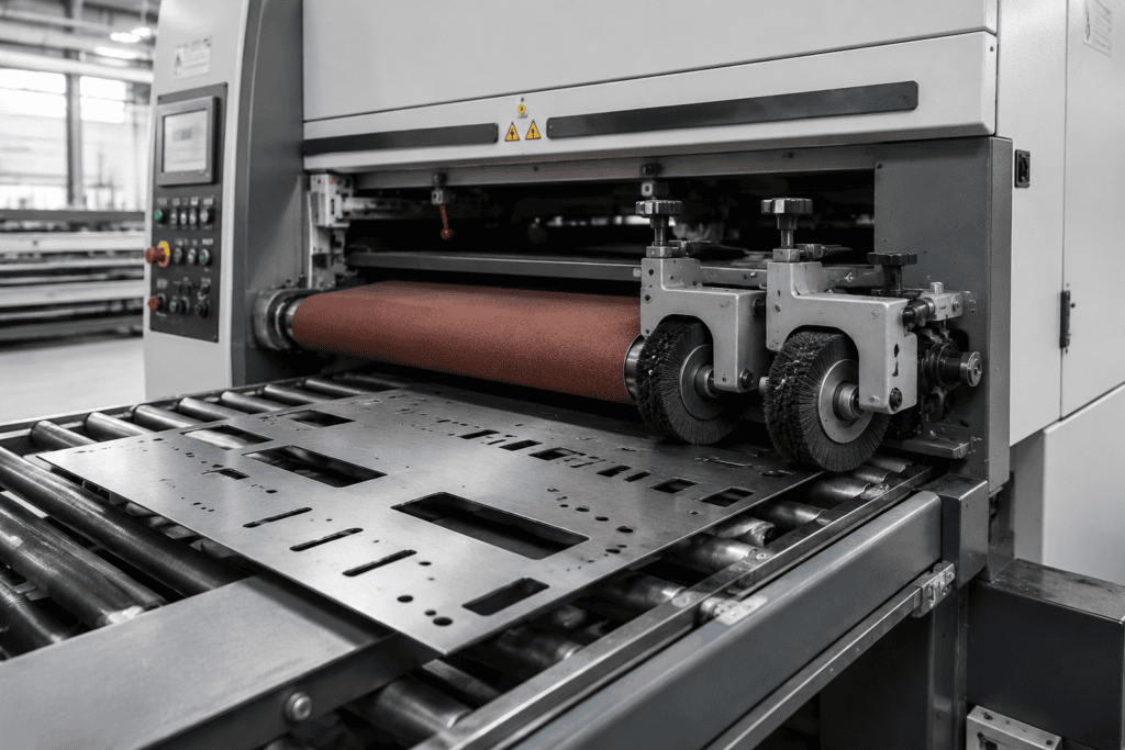
Edge rounding is the process of converting the sharp edge left by laser cutting, punching, machining or casting into a controlled radius, typically in the R0.1 to 0.5 mm range and up to roughly R2.0 mm for heavy corrosion duties. It is not the same as deburring. Deburring removes the unwanted burr; edge rounding goes further and produces a defined geometric feature that can be called out on a drawing, produced repeatably and verified with a gauge. The distinction matters: a merely deburred edge can still cut a hand, peel a powder coating or start a fatigue crack; an edge with a true radius will not.
Three routes dominate industrial practice: wide brush and rounding-block machines for sheet metal, mass finishing for batch parts, and robots with force-controlled spindles tracing a programmed arc for large castings, weldments and housings. This guide covers all three, then measurement, drawing callouts and route selection.

Edge Rounding at a Glance
| Parameter | Typical range | Notes |
|---|---|---|
| Common radius band | R0.1 to 0.5 mm | Coating prep high end, light edge breaking low end |
| Heavy-duty radius | Up to R2.0 mm | Structural and hot-dip galvanizing work; rotary brush machines |
| Position in chain | After deburring | Burrs come off first, then the edge gets its radius |
| Route 1: Sheet metal | Brush rotors, disc brushes, rounding blocks | All outer and inner contours in one pass |
| Route 2: Batch parts | Vibratory bowls, barrels, centrifugal finishers | Natural radii; grow with cycle time and media aggressiveness |
| Route 3: Large parts | Robotic spindle with force control | Directed radius on selected edges; path-driven geometry |
| Verification | Radius gauges, contour probes, cross-sections | Gauge for speed, contour for records, section for arbitration |
The useful framing: an edge radius is a specification, with a producer side, a number and an acceptance method. Shops that treat rounding as “just make it not sharp” fail audits.
What Edge Rounding Actually Means
After cutting, an edge is rarely a clean 90-degree intersection of two surfaces. Laser cutting leaves a striated edge with sharp corners top and bottom, punching shears a rolled crest onto the edge, milling leaves a feather where the cutter exits. None of these is a radius, and none is acceptable on coated, handled or fatigue-loaded parts.
Edge rounding, called edge radiusing or edge breaking in shop language, replaces that unstable corner with a smooth convex arc joining the two faces. A radius is defined by exactly one number, the radius of that arc, which is why it can be toleranced on a drawing like a hole diameter or a fillet. Practice separates two intensities: edge breaking knocks the worst sharpness off at the low end of the R0.1 to 0.5 mm band, while full rounding drives the radius toward and beyond 0.5 mm for parts that will be painted, galvanized or handled.
The operation always follows burr removal. Rounding a heavily burred edge folds the burr into the radius instead of removing it, leaving an inclusion under the coating and a stress riser in the base material. Deburr first, round second: sheet metal machines combine both stations in one line.
Why the Radius Is a Functional Specification
Edge rounding sits inside the broader map in our surface finishing processes guide; for how much removal is legitimate on an edge, see deburring vs grinding.
Rounded edges look better, but every serious reason to round one is functional.
Coating adhesion and coverage. Liquid paint, powder coating and zinc plating all thin out as they wrap a sharp corner. On a zero-radius edge the dry film thickness often drops to a fraction of its nominal value on the adjacent faces, and many coatings pull back from the crest entirely. The edge becomes the thinnest, least protected point on the part, exactly where corrosion starts. Raising the radius to around 0.5 mm gives the coating a surface it can build to full thickness over, and standards encode this: DIN EN 1090, the execution standard for steel structures, requires an edge radius of at least 2 mm where corrosion protection depends on it.
Fatigue life. A sharp edge is a stress concentrator. On shafts, springs, gears and brackets under cyclic load, the zero-radius edge concentrates stress at the surface, where fatigue cracks initiate. Increasing the radius to even 0.2 or 0.5 mm measurably lowers the concentration, which is why fatigue-critical drawings specify a radius value instead of a vague “break sharp edges” note.
Handling and assembly safety. A freshly cut sheet edge is a knife, and it injures the operator, the welder, the assembler and eventually the end user. Sharp edges also saw through cable jackets, hose covers and O-ring seals inside machines, causing failures far from the original cut. Rounding removes a whole class of injury and warranty events for one finishing pass.
Flow and cleanliness. In hydraulic manifolds and food or pharma contact parts, sharp internal edges shed particles into the fluid, add turbulence and pressure drop, and form crevices that resist cleaning validation.
Route 1: Sheet Metal, Brush and Rounding Block Machines
This route exists because fabricators cut thousands of flat parts per day and cannot touch an edge by hand at that volume. Parts pass through a wide machine on a conveyor, and every edge, outer contour and inner cutout alike, is processed in one or two passes. Our sheet metal deburring machine guide covers the machine classes; here the focus is how each tool forms the radius itself.
Rotary brush rotors. A carousel of abrasive-filled rotary brushes spins above the passing sheet, dragging abrasive lamellas across the edge from multiple directions and eroding the corner into a radius uniformly around the contour. Rotary brushes give the best and most consistent rounding of the sheet metal tools, and current machines reach radii up to about 2.0 mm, enough for DIN EN 1090 compliance at speed. Coarse grits remove fast but leave a rougher surface; fine grits cut slower, leave smoother finishes and suit small, thin parts.
Disc brushes. Flat brushes with abrasive filaments rotate above the conveyor and strike the edge as the part passes. Mechanically simple, cheap and reasonably uniform, they are the standard on entry-level machines for smaller parts. Their limits are brush life, removal rate and reach into inner contours: a disc brush processes only the edges it can see from above, so nested cutouts round less than open profiles.
Rounding blocks. Consumable blocks with embedded abrasive, carried on circulating belts, contact the sheet from above and below simultaneously, so one pass rounds both faces of the edge, the fastest and usually most economical process per part. Pressure rollers keep even slightly warped sheets engaged. Two constraints apply: the process needs a minimum part length for stable engagement, and edges perpendicular to feed round slightly more than edges parallel to it, which nesting orientation absorbs when the print tolerances the radius tightly.
Route 2: Machined and Batch Parts, Mass Finishing Radii
Machined parts, small stampings, sintered components and die castings follow a different route: short edges, three-dimensional features, high volumes. Mass finishing, vibratory bowls, tumbling barrels, centrifugal disc and drag finishers, produces edge radii as a natural consequence of media rubbing the workpiece everywhere at once, rounding every accessible edge while smoothing surfaces and clearing the last burr fragments. Our mass finishing guide works through the variables; for radius formation, media selection dominates, and the deburring media guide maps the chemistry. The rules:
- Media size relative to features. Media must enter the holes and slots whose edges need rounding without wedging in them; lodged media rounds nothing and blocks flow for the batch.
- Media shape and cut. Aggressive ceramic media forms radii faster; spherical or pre-worn media gives gentler, more polished edges. Fast-cut formulations reach the top of the mass finishing band, roughly R0.3 mm, in standard cycles.
- Cycle time is the radius dial. A 30-minute vibratory cycle might deliver R0.05 to 0.1 mm of edge break; two hours of aggressive ceramic media in a high-energy centrifugal disc can push toward R0.3 mm. Beyond that band the process improves finish long before it grows the radius, so promising R0.5 mm from a tumbler means paying for hours per batch.
- Protect delicate features. The same rubbing that rounds edges can dull threads, so precision features need divider baskets or media isolation.
These radii are real, repeatable and cheap per part, but statistical rather than directed: the process cannot round one edge and leave another sharp, and the radius lands in a band rather than on a nominal, so prints should call a range, e.g. R0.1 to 0.3 mm.
Route 3: Large and Complex Parts, Robotic Path-Controlled Rounding
Castings, weldments, large machined housings and high-mix parts fit neither a brush machine nor hours in a bowl. For these, rounding becomes a programmed motion: a six-axis robot carries a spindle-mounted brush or flap wheel along a path that traces an arc across each specified edge, while force control holds the tool against the edge at a set normal pressure. Because the path is programmed, the robot rounds exactly the edges the print specifies and leaves datum faces, sealing surfaces and bore walls untouched. The platform is the one described in our robotic grinding guide. The rounding-specific differences:
- Force control does the geometry. A brush held at constant force conforms to part-to-part variation in the casting or weld line and still produces a consistent radius, viable on cast parts whose edges drift a millimeter or more between shots. Rounding passes run at light contact forces, single-digit to low-tensile newtons, far below stock-removal grinding pressures.
- Tool choice sets the radius ceiling. Abrasive filament brushes produce the R0.1 to 0.5 mm band with excellent surface quality; flap wheels reach larger radii on thicker edges. Changing radius on a revision is a tooling and offset change, not a machine change.
- Directed rounding protects functional edges. On a gearbox housing the robot can radius outer casting edges and bolt-hole rims while skipping bearing bores and the sealing plane. No bowl or brush machine can make that distinction.
- Each edge is programmed as an arc, generated offline from the CAD model, with probing or in-cycle locating compensating casting drift so the arc lands on the real edge.
For the wider automation picture, see our robotic deburring overview.
Measuring and Accepting the Radius
A radius that is not measured is a hope, not a specification. Production inspection uses three methods in escalating order of cost.
Radius gauges. Leaf-style gauges with stamped radii from about R0.1 mm upward are the shop-floor standard: hold the gauge against the edge under angled light and check for a visible gap. Fast and adequate for most fabrication work, with two caveats: gauges read in discrete steps, so a true R0.37 mm edge reads “between R0.3 and R0.4”, and the result depends on the inspector’s eye.
Contour measurement. A contour profilometer drags a stylus across the edge and software fits the radius from the recorded profile. The method for documented acceptance: it produces a traceable number, supports tighter tolerances, and catches asymmetric radii, common since a rounding block or robot pass can lean to one face. Optical systems do the same without contact.
Cross-sectioning. The arbitration method: mount the part or a coupon processed with it, section perpendicular to the edge and measure under a microscope. Destructive and slow, but the only method that shows what is under the surface: burr fragments folded into the radius, a rolled edge from over-aggressive brushing, recast material smeared rather than removed.
Two subtleties cause most arguments. First, radius is not chamfer width or removal depth; a print calling R0.5 requires an arc, and a 0.5 mm chamfer is a nonconformance even when it looks round. Second, verify at multiple locations, because every route rounds some orientations better than others.
Edge Rounding vs Chamfer: What the Drawing Actually Says
Drawings use three related callouts, and confusing them creates rework.
“Break edge” or “break sharp edges” is the loosest note: remove the sharp corner, typically leaving a radius or chamfer of a few hundredths to a tenth of a millimeter, often bounded by a value like 0.2 max. It defines no shape, only that no knife edge remains.
A chamfer callout, 0.5 x 45 degrees or C0.5, specifies a flat bevel at an angle across the edge. Chamfers are produced deterministically by milling or turning and are the right callout where an edge must clear a mating part or guide an O-ring into a bore. But a chamfer terminates in two fresh edges, bevel-to-face on each side, and those can still be sharp. For coating durability and fatigue a chamfer is an intermediate step, not a substitute; many prints call a chamfer followed by a radius note, meaning the chamfer removes bulk material and the rounding pass converts what remains to arcs.
A radius callout, R0.3, R0.5 or an edge radius range, specifies the arc. It is the correct callout for coating prep, fatigue life, handling safety and flow, because those failures are driven by stress and coating thinning at a corner, which only a convex arc addresses. When the drawing is silent and the part will be coated or handled, the question worth raising is whether “deburr” really means “radius”.
The measurement follows the geometry: a chamfer is checked by linear width and angle, a radius by fitting an arc. Accepting one against the other passes parts that will fail for the reason the callout exists.
Choosing Between the Three Routes
The decision follows part size and geometry, volume, material, and the radius specification itself.
- Flat cut sheet parts in quantity go to the sheet metal route. Parts coming off a laser, punch or plasma table amortize a through-feed brush machine across the whole shop. Edge break to R0.5 mm is routine; specify a rotary brush machine if the print demands R1.0 to 2.0 mm or DIN EN 1090 compliance. The deburring machine types guide breaks down the machine classes.
- Small, rigid, high-volume parts with features on all sides go to mass finishing, provided every edge needing the radius is media-accessible and no feature is damaged by tumbling. Specify statistical radii in the R0.05 to 0.3 mm band and validate with a time study before quoting the top of it.
- Large parts, mixed parts, or parts where only some edges get the radius go to the robotic route. The break-even is mix: one robot serving several part numbers with directed edges beats dedicated machines when each family is too small to justify its own through-feed equipment.
- The routes cooperate more than they compete. A robot that rounds casting edges can run a grinding program on gates the next cycle, and a brush line often feeds welded assemblies that later get robotic rounding.
Two cost notes from practice. The cheapest radius is the one designed in: an edge allowed to stay sharp needs no processing, so radius callouts should exist only where a function justifies them. And validate on real parts before buying: every reputable builder runs samples, and that sample report, radius measured at named locations, becomes the acceptance criteria in the purchase order.
Frequently Asked Questions
How much radius does edge rounding actually produce?
On sheet metal machines, light edge breaking starts around R0.1 mm, coating-preparation radii sit at roughly R0.3 to 0.5 mm, and rotary brush machines reach up to about R2.0 mm for structural work. Mass finishing produces statistical radii typically between R0.05 and 0.3 mm depending on media, machine energy and cycle time. Robotic rounding produces whatever the tool and program are set for, most commonly R0.1 to 0.5 mm with brushes.
Is edge rounding the same as deburring?
No, and the sequence matters. Deburring removes the burr left by cutting; edge rounding then converts the cleaned but still sharp corner into a defined radius. Rounding over an unremoved burr folds it into the edge, so production deburrs first and rounds second, often in one machine or cell.
What edge radius do I need before powder coating or galvanizing?
For liquid and powder coating, fabricators standardly target at least R0.5 mm so the film builds to near-nominal thickness over the edge instead of thinning at the crest. For hot-dip galvanized structural steel, DIN EN 1090 calls for an edge radius of at least 2 mm where corrosion protection depends on the coating.
Can vibratory finishing produce a true specified radius?
It produces a real radius, but a statistical one: the radius lands in a band set by media aggressiveness and run time rather than on a single nominal, and every accessible edge rounds simultaneously. For prints calling a range, R0.1 to 0.3 mm for example, mass finishing is the lowest-cost-per-part route. For a tight-tolerance nominal, or when only certain edges may be rounded, use a directed process, a brush machine or a robotic path.
How is an edge radius inspected on the shop floor?
The quick check is a leaf radius gauge held against the edge under angled light, workable from about R0.1 mm upward in discrete steps. Contour profilometers and optical systems fit the actual arc and generate documented numbers. Cross-sectioning a mounted sample is the arbitration method, because it shows folded burrs and smeared material that gauges cannot see.