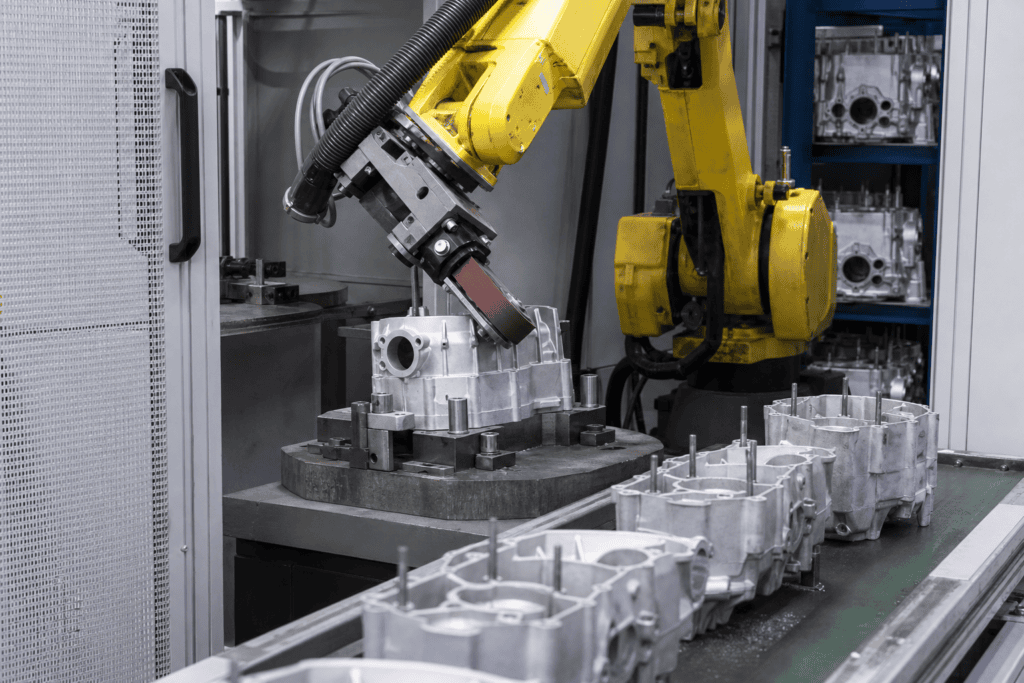
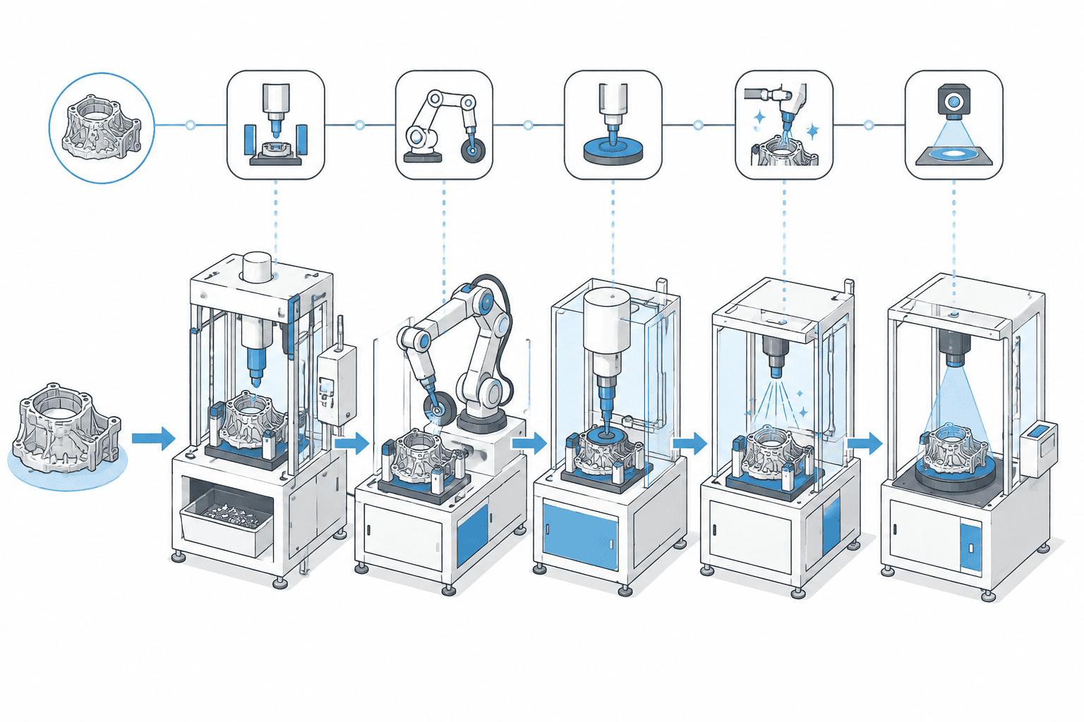
Die casting deburring automation—often called fettling automation—is the robotic handling of everything that happens to a casting between the moment the extractor pulls it out of the die and the moment it lands in a machining fixture: removing gates, runners, and overflow pads, clearing parting-line flash, stepping down core-shift and mismatch ridges, and cleaning the datum and clamping faces that downstream machining depends on. It is not one machine. It is a chain of operations—trim, rough grind, finish deburr, datum cleanup, inspection—whose links have to be timed against the die casting machine’s own cycle, and the robot is the thread that runs through all of them.
That chain view matters because most plants buy fragments of it. A trim press here, a manual fettling bench there, a deburring robot bolted into the middle, each purchased against a local crisis and none of them timed against the shot cycle of the machine feeding them. The result is a cell that works beautifully for three weeks and then becomes the bottleneck everyone works around. This article lays out the whole chain as one system: where the flash comes from, what each stage removes, how the casting process and the alloy change the cell, and when the investment pays. If you are new to the equipment itself, start with our primer on what robotic deburring is, then come back for the die-casting-specific layer.
We build these cells at UBright Solutions in Nanjing, and the application library we draw on later in this article is our own—cylinder blocks, oil pans, transmission housings, and cast iron gear cases that came through this exact chain.
Why Die Castings Cannot Ship Without Fettling
High-pressure die casting creates its own finishing workload by physics, not by sloppiness. Molten aluminum enters the cavity at gate speeds of roughly 20–60 m/s, and the intensification phase squeezes the metal at several hundred bar after the cavity fills. Any clearance in the die—an aging parting line, a worn slide or core, an exhaust groove—lets metal escape during that squeeze. What solidifies in those gaps is flash: typically 0.1–0.8 mm thick along the parting line on a healthy die, running over 1 mm on a die nearing refurbishment. The same shot leaves gate stubs at the ingates, overflow pads at the cavity edges, and vent fins at the parting face, all attached to the part when the ejector pins push it out.
The downstream plant does not accept any of it. A customer machining your casting clamps on datum faces and bores that must be flat, clean, and free of raised material; a mismatch step of even 0.3–0.5 mm can lift the part in the fixture and scrap it at the spindle. Burrs left at oil passage mouths travel into hydraulic and transmission circuits as hard particles. Sealing flanges—the oil pan rim, the valve body face—leak if the edge condition varies along the perimeter. And burr spec disputes with a customer’s quality department consume engineering hours that never appear in the fettling cost center.
The final reason is the crew. Fettling benches run all shift in aluminum dust, at 85–105 dB, with vibrating hand tools on hot-cycled castings. It is the hardest station in a die casting plant to staff and the one with the highest injury and turnover profile. Plants rarely automate fettling because a spreadsheet told them to; they automate it because the sixth operator in two years just quit.
The Post-Casting Chain, Stage by Stage
Break the chain into its stages and each one has a defined machine, a defined input condition, and a defined takt.
Extraction and cooling. The casting leaves the die at 150–250°C for typical aluminum alloys. Whether it enters fettling hot or after a cooling loop is a real decision: hot burrs are softer and cut faster, but the cell needs heat-tolerant fixtures, grippers, and tooling, and thermal growth of 0.1–0.3 mm across a 500 mm part must be accounted for in the finishing offsets.
If your flash problem is on rubber or plastic parts rather than cast metal, that is a different physics altogether—see our cryogenic deflashing guide.
Gate and runner trimming. The bulk removal of gates, runners, overflow pads, and vent fins happens first, because grinding through a 6–12 mm runner stub with abrasives is the most expensive possible way to remove it. A trim press with a part-specific die does it in one stroke, 8–15 seconds per shot. Where press tooling cannot be justified—a high-mix plant running many low-volume parts—the robot substitutes: sawing, shearing, or milling the gates with a spindle, 20–60 seconds per part, with zero die changeover instead of a press tool per part.
Rough grinding. Parting-line flash and mismatch ridges come off with abrasive contact. Robot-held parts run along belt machines in the 40–80 grit range; where the geometry demands it, a spindle with a coarse burr or flap tool works the ridge directly. This stage sets the takt for most cells—30–60 seconds for a mid-size automotive housing—and exists to remove tenths of a millimeter economically, not to finish anything.
Finish deburring. Hole mouths, rib roots, internal cavity edges, and bore chamfers need small tools at speed: electric spindles in the 20,000–40,000 rpm class carrying end mills, rotary burs, or brushes, reaching features the belt could never touch. This is where force control earns its keep, holding contact within roughly ±1–5 N so a 0.2 mm burr and a 0.6 mm burr both finish to the same edge.
Datum and sealing-face cleanup. Machining datum faces, clamping points, and sealing flanges get directed, light, path-controlled passes rather than bulk grinding. On thin-wall parts this is the most delicate stage of all—the oil pan flange discussion later shows why.
Inspection and marking. Vision checks for residual flash and edge condition; depth or profile checks on specified edges; date-wheel or laser marking that binds the finished part to its die shot. The chain ends with a part a machining plant can load without a human ever looking at an edge.
High-Pressure, Low-Pressure, Gravity: One Word, Three Fettling Problems
“Casting finishing” gets used as if all castings fettle alike. They do not, and the casting process is the first thing to settle before specifying a cell.
| High-pressure die casting | Low-pressure casting | Gravity / sand casting | |
|---|---|---|---|
| Typical flash | 0.1–0.8 mm, along full parting line | 0.05–0.2 mm, sparse | 1–3 mm fins, irregular |
| Bulk removal | Trim press or robotic gate milling | Machined or sawn gate/riser | Fettled by grinding, chiseling |
| Dominant finishing task | Parting line, holes, ribs, datum | Gate scar, local seams | Parting line, sand-burned zones |
| Typical cell | Trim + robot grind/deburr | Lathe/mill + robot polish | Heavy rigid grinding |
High-pressure castings are thin-walled (2–4 mm typically), geometrically rich, and flash-prone across every parting surface—exactly the profile that suits a robotic trim-grind-deburr chain of the kind described above. Low-pressure parts—wheels, suspension components—see far less flash but carry a substantial gate scar where the feedstalk was cut, so the emphasis shifts toward machining that scar and polishing specified surfaces rather than clearing flash everywhere. Gravity and sand castings—the cast iron gear housings among them—are a third world: flash measured in whole millimeters, dimensions that wander with mold wear, and wall sections thick enough that the cell needs rigid grinding contact rather than light compliant strokes. The robotic grinding guide covers that heavy-contact regime, including the rigid-versus-compliant tooling decision, in depth.
The practical consequence: a cell tuned for HPDC housings will under-perform on sand-cast iron, and vice versa. Specify against your casting process, not against “castings.”
Inside the Robotic Fettling Cell
Two topologies cover almost every die casting installation, split by part weight.
In the first, the robot holds the part and presents it to stationary machines—belt grinders, brushing stations, buffing wheels. This suits castings up to roughly 15–20 kg and gives you high path accuracy, simple stationary tooling, and the option to swap process stations without touching the robot program. In the second, the part sits in a fixture and the robot carries the spindle to the work. That suits heavy housings and any part needing internal cavity access, at the cost of managing tool deflection. Many automotive cells run both: part-in-hand against the belts for the parting line, part-in-fixture with a right-angle or long-neck spindle for bores and internal ribs.
The workstation architecture matters as much as the robot. A dual-station rotary table—part processing on one face, unload and reload on the other—hides the handling time inside the processing time and is the standard answer when the shot cycle is 60–90 seconds. Our own 6-axis dual-station deburring equipment is built around exactly that pattern for automotive castings. When the cycle allows it, one robot can also serve two or three die casting machines with a linear track, collapsing the capital per machine.
Force control is the third pillar. Castings vary—flash thickness moves with die condition across a production run, and part position varies with how it sits in the fixture. A rigid path with fixed offsets either misses the thin days or gouges the thick ones. A force-controlled spindle, or a passive compliant float built into the tool interface, keeps contact pressure inside a ±1–5 N band and turns incoming variation into a constant edge instead of a scrap generator.
Aluminum, Magnesium, Zinc: Same Chain, Different Safety and Tooling Rules
Die casting plants run three alloy families, and the cell that is safe and productive on one can be wrong on another.
Aluminum—ADC12, A380, and their kin—generates fine, combustible dust when ground. Aluminum dust clouds ignite at concentrations on the order of tens of grams per cubic meter, and settled layers burn ferociously when disturbed, which is why wet-type dust collection with grounded, conductive ducting is the default for robotic aluminum fettling cells, and why NFPA 652/654 in the United States and ATEX zoning in Europe shape the enclosure, the extraction velocities, and the housekeeping regime of the installation. Occupational limits for respirable aluminum—the fraction below roughly 10 µm—run in the 1–5 mg/m³ range depending on jurisdiction, but in practice the explosion risk, not the health limit, is what drives cell design.
Magnesium inverts the wet-collection logic. Magnesium fines and chips react with water to release hydrogen, so the wet scrubber that protects an aluminum cell becomes a hazard on a magnesium one. Magnesium fettling cells run dry collection with spark and flame control, inert handling of fines, and strict segregation of swarf. The alloy is also more notch-sensitive, so tool geometry and contact force windows differ from aluminum practice even though the chain stages look identical on paper.
Zinc and zinc alloys—Zamak 3 and 5—behave differently again. Low melting point and high toughness mean the burr does not cleave off the way aluminum flash does; it rolls, smears, and work-hardens, and it loves to stick to cutting edges. Zinc cells lean harder on scrapers, brushed finishes, and free-cutting tool geometries, and run lower spindle speeds than the same features need in aluminum.
None of this changes the chain. All of it changes the extraction system, the tool crib, and the risk assessment—three line items that belong in the specification, not in the commissioning punch list.
Integrating With the Die Casting Machine: Takt, Traceability, Fixture Families
The fettling cell is downstream of a machine that fires on its own clock, and integration failures usually trace to ignoring that clock.
Takt matching comes first. A production die casting machine completes a shot every 60–120 seconds for typical automotive work, longer for large structural parts. A single-part cell finishing in 30–60 seconds has headroom; a cell at 100 seconds per part is already marginal on a 90-second machine and needs either the dual-station buffering described above or an honest decision to let the cell serve fewer shots per hour with a WIP queue absorbing the difference. That queue is itself a design item: it decides whether a cell stoppage idles casting production within minutes or within a shift.
Traceability is the second integration layer, and automotive customers audit for it. The finished casting should carry a mark—date wheel, dot peen, or laser—that binds it to a die shot, and the cell’s program records should connect that mark to the finishing cycle that ran on it. When a burr complaint surfaces on a machined part weeks later, tracing the casting back to die, shot count, and fettling cycle is the difference between a contained quality claim and a month-long fishing expedition.
Fixture family management decides whether a high-mix plant survives. A die caster running 10–15 active part numbers does not buy ten cells; it buys one cell with quick-change fixturing, part programs called up by barcode scan, and changeover inside 10–30 minutes. The fixture library then becomes a living asset—every new part number is a new fixture, a new program, and a proving run, and the engineering cost of that pipeline belongs in the cell’s operating budget from day one.
The Investment Case in a Die Casting Context
The financial structure of a fettling automation project is covered in our deburring automation ROI guide: three ledgers, labor substitution, consistency and quality, and the hidden costs of the manual process, each with number ranges and worked examples. What changes in the die casting context is the weight distribution across those ledgers.
The labor ledger is heavier here than in machining-adjacent deburring, because fettling crews run in shifts that mirror the casting machines—two or three dedicated operators per shift, two to three shifts, so a single cell can absorb four to nine staffed positions—most of which convert to net releat positions. The hidden-cost ledger is also heavier: aluminum dust exposure monitoring, hearing conservation programs for 85 dB-plus benches, hand-arm vibration surveillance, and the injury and turnover profile of the hardest-to-staff station in the plant are all recurring annual costs that the manual process pays and the cell deletes. The consistency ledger tends to be lighter than buyers expect—die castings arrive with genuinely variable edge conditions, so the cell removes variation caused by fatigue and technique but not variation caused by the die itself.
On capital: a single-station cell for a convergent part family lands in the $150,000–250,000 range; a dual-station high-mix cell with a full fixture library and offline programming runs $300,000–450,000. Against a multi-shift fettling crew’s three-ledger benefit stack, 14–30 months is the honest planning band—the guide’s worked examples show how to compute your own rather than trust a vendor’s single number.
What Our Application Library Shows
The clearest way to see the chain is through the castings that have run through it. Our application library documents these projects part by part; four of them map the territory well.
| Part | Alloy / process | Finishing focus |
|---|---|---|
| Engine cylinder block | Aluminum HPDC, 400–700 mm | Outer contour, bore and water-jacket openings, oil passage mouths, rib transitions |
| Engine oil pan assembly | Aluminum HPDC, thin-wall, 350–700 mm | Sealing flange perimeter, bolt holes, drain boss, internal ribs |
| CVT transmission main housing | Aluminum HPDC, large 3D | Cavity openings, bearing and shaft hole edges, sealing flanges, mounting bosses |
| Gearbox housing | Cast iron, gravity/sand | Parting line, inner cavity burrs, opening and base feet edges |
Read together, the four say three things. First, the chain scales: the cylinder block and CVT main housing carry the full trim-grind-deburr load on large three-dimensional castings, while the oil pan shows the same architecture working on a thin-wall part where the critical feature is a single sealing flange that must finish consistently around its entire perimeter—too much force anywhere on that rim and the sealing surface is compromised. Second, internal access drives tooling: bearing holes, oil passages, and crankcase cavities in the transmission and engine parts are reachable only with angled and long-neck spindles, which is why the robot-holds-tool mode exists at all. Third, the cast iron gearbox housing proves the architecture crosses casting processes: heavier contact, heavier abrasives, the same chain. Its parting line and cavity finishing before coating run on the same cell logic as the aluminum parts.
When to Move: A Decision Checklist
The plants that succeed with fettling automation share observable preconditions. Check them before any vendor quote.
Shot volume is stable. One die pair producing 8,000–20,000+ shots per month, or a family of dies at that combined rate, amortizes the cell. A machine whose monthly volume swings by a factor of three cannot be timed against anything.
The part family has converged. Ten to fifteen active numbers with stable geometry and real production lives justify a fixture library. Fifty numbers in flux means the program and fixture pipeline eats the labor savings—this is the failure mode, not the robot’s accuracy.
The labor line has been crossed. Roughly two or more dedicated fettling operators across two or more shifts, fully burdened, is where the three ledgers start to clear the capital inside two years. Below that, better manual tooling and better dies are the honest answer.
The upstream input is consistent. Flash that varies from 0.1 mm to 1.5 mm across a die’s life is a die maintenance problem no finishing cell solves; it merely exposes it. Die condition, die temperature control, and shot-to-shot repeatability gate everything downstream.
And know the honest exclusions: prototype and development castings, volumes under roughly 50 parts per day, and geometries that change faster than programs can be written. A cell on an unconverged part family is an expensive manual station with a robot in it.
FAQ
Does robotic fettling replace a trim press?
No, and in high-volume plants they run in series. The trim press removes gates, runners, and overflows in one stroke where volumes justify part-specific tooling; the robot cell handles the flash, mismatch, and detail finishing the press cannot reach. In high-mix, lower-volume plants, robotic gate milling replaces the press economically—one program instead of one trim die per part.
Can a robot deburr the internal cavities of a die casting?
Yes, with the right tooling mode. Robot-held right-angle and long-neck spindles reach crankcase cavities, bearing bores, and internal ribs on parts like transmission housings; the limits are reach-versus-clearance tradeoffs and tool change time, not the robot’s path capability. Features beyond spindle reach get a second fixture pass—part reorientation is the standard workaround.
Should castings enter the cell hot or cold?
Both are run in production. Hot castings—150–250°C out of the die—cut faster because the flash is softer, but demand heat-rated fixtures and thermal-offset compensation of 0.1–0.3 mm on a 500 mm part. Cold castings give stable geometry and simpler tooling at the cost of buffer time and slower cutting. The layout usually decides it: cells at the machine exit run hot, centralized cells cold.
What cycle time should I plan per part?
As a planning band, 20–60 seconds per part for a mid-size automotive casting on a dual-station cell, with complex housings running toward the top of the band. The governing number is not the part’s time but the ratio of cell time to shot cycle—anything within roughly 70% of the die casting machine’s interval needs buffering or a second station.
Is one fettling cell enough for several die casting machines?
Often, yes. Machines on 60–120 second cycles leave enough slack for one robot on a linear track, or one dual-station cell with input buffering, to serve two to three machines. The design limit is total shots per hour, not machine count—add up the combined demand, add the changeover overhead if part families alternate, and size the cell against that number.