When Loading Time Starts Eating Your Output
A single-station machine pays for a hidden tax on every part: while the spindle finishes a casting, nothing is being loaded, and while the operator swaps parts, the spindle waits. At low volumes nobody notices. At two shifts a day on a stable part family, that idle window compounds into real lost capacity. The LDW-6R dual-station machines exist to cancel it. One station is always in the working zone while the other is being loaded or unloaded, so the spindle never stands still for part handling.
Two builds are offered on the same 6+2 axis platform: the LDW-6R-5T-70-2 with X700 x Y700 x Z650 mm travel and a five-spindle head, and the larger LDW-6R-6T-90-2 with X900 mm travel and six spindles. Both carry the six-axis control, ±0.02 mm/300 mm processing accuracy, and the same finishing toolset as the single-station LDW-6R series, so nothing about the process itself is compromised by the second station. What changes is the production organization around it.
Two Stations, One Working Zone
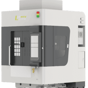
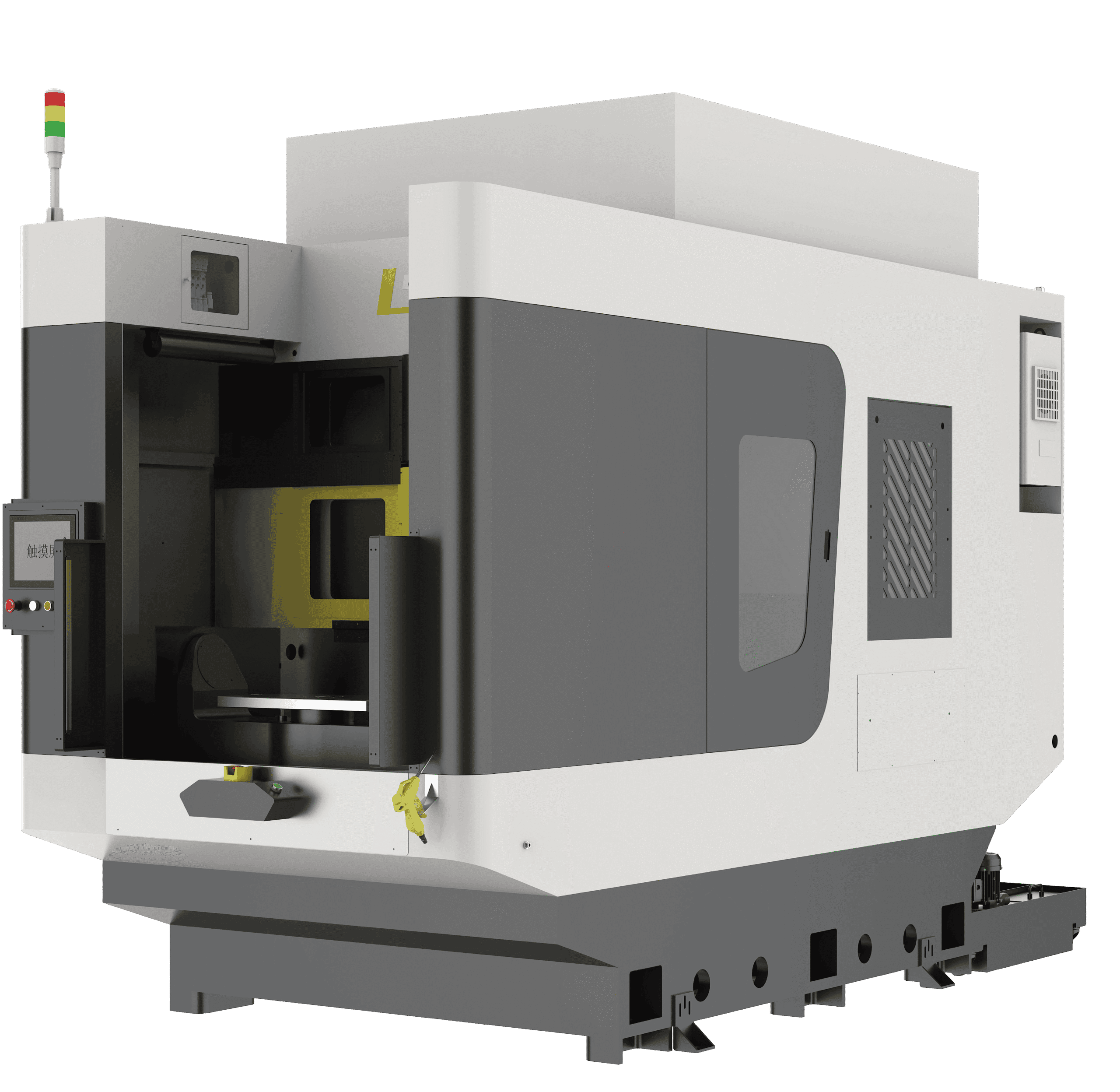
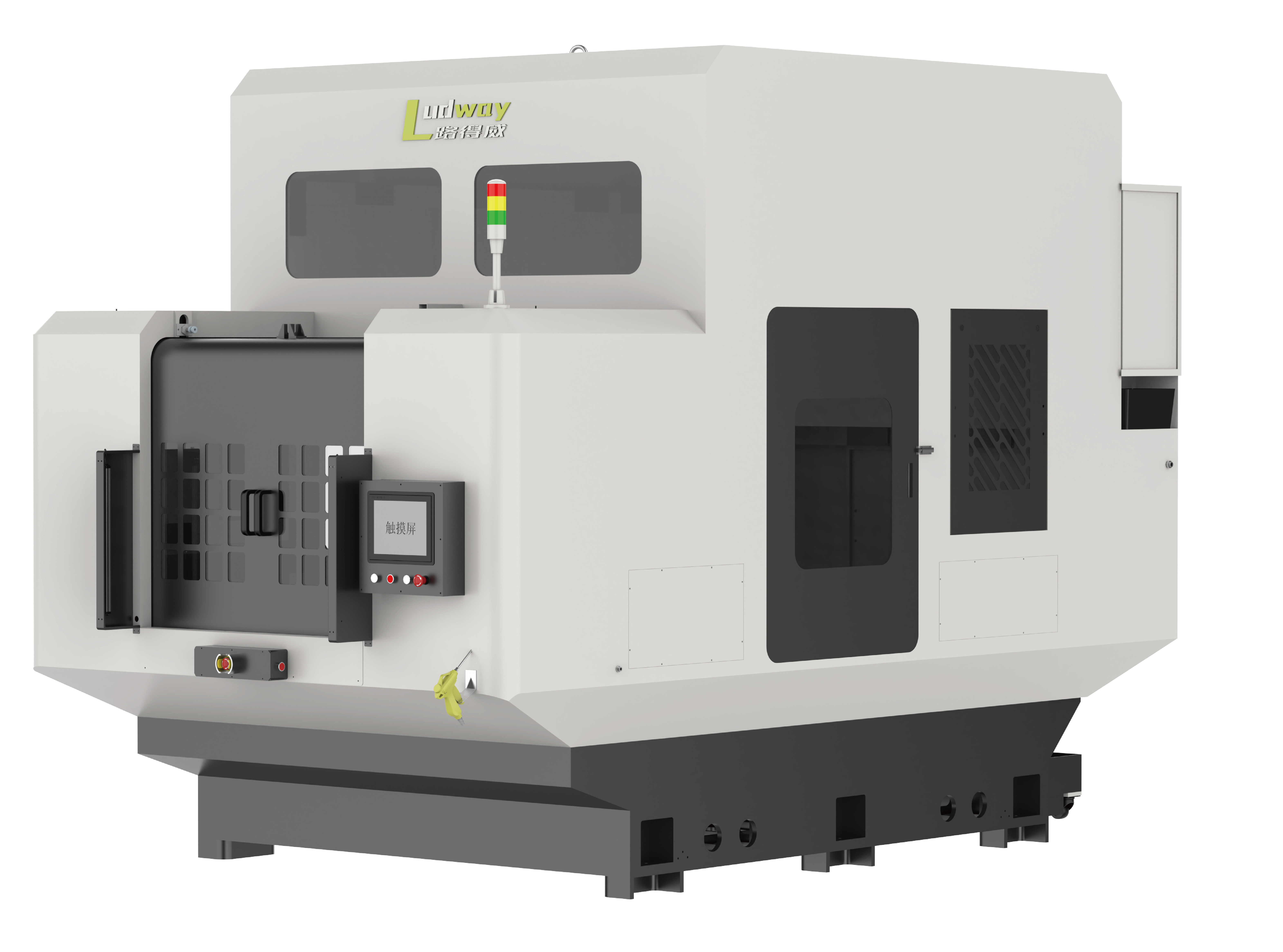
Mechanically the machine places two independent workstations alongside the machining envelope, with the column serving first one and then the other. The cycle runs like a relay: the fixture on station A closes, the spindle runs its taught program, and the moment the head retracts and indexes, the machine is already presenting station B, which was loaded during the previous cycle. The operator works in a steady rhythm at the front of the machine while cutting continues behind the guarding, and there is no waiting on either side.
For illustration only, with real figures set by the part and the tool path: a casting that needs 90 seconds of cutting and 40 seconds of handling produces one part every 130 seconds on a single station. On the dual-station layout the 40 seconds hide inside the 90, and steady-state output approaches one part per cutting cycle, roughly 40 percent more from the same footprint and the same process. The physical machine grows accordingly, L3570 x W1700 x H2400 mm for the 70-2 and L3720 x W2050 x H2780 mm for the 90-2, and machine weight rises to 6.5T and 7.2T respectively. Whether that trade pays is a volume question, and it is worth running honestly before specifying.
Everything that supports long unattended runs is built in: full protective covering over the motion assemblies, automatic lubrication, and a wet chip hopper that separates coolant from metal chips so continuous production does not bury the work area in swarf. The HMI reports both stations’ status, production counts, alarms, and tool wear, which matters more when the machine is treated as a capacity asset rather than a job-shop tool.
Specifications of the Two Builds
| Category | Specifications | LDW-6R-5T-70-2 (70 Dual Workstations) | LDW-6R-6T-90-2 (90 Dual Workstations) |
|---|---|---|---|
| Basic Machine Parameters | Model | LDW-6R-5T-70-2 | LDW-6R-6T-90-2 |
| Overall Dimensions | L3570 x W1700 x H2400 mm | L3720 x W2050 x H2780 mm | |
| Equipment Travel | X700 mm + Y700 mm + Z650 mm | X900 mm + Y700 mm + Z650 mm | |
| Idle Speed | 32000 mm/min | 32000 mm/min | |
| Processing Speed | 1000-10000 mm/min | 1000-10000 mm/min | |
| Distance Between Spindle Nose & Worktable | 50-550 mm | 50-550 mm | |
| Spindle Cooling Method | Oil Cooling / Air Cooling | Oil Cooling / Air Cooling | |
| Air Pressure Requirement | ≥0.55 MPa | ≥0.55 MPa | |
| Number of Spindles | 5 | 6 | |
| Precision & Drive Parameters | Processing Accuracy | ±0.02 mm/300 mm | ±0.02 mm/300 mm |
| Drive Motor Configuration | 1.5 kW x2 + 4.4 kW + 750 W x5 | 1.5 kW x2 + 4.4 kW + 750 W x6 | |
| Total Machine Weight | 6.5T | 7.2T | |
| Control & Motion System | Control System Brand | Xindai (Taiwan) | Xindai (Taiwan) |
| Total Control Axes | 6+2 | 6+2 | |
| Handwheel Configuration | Standard Equipped | Standard Equipped | |
| Lubrication System | Automatic Lubrication Device | Automatic Lubrication Device | |
| Spindle Motor Parameters | Spindle Brand | Ludway | Ludway |
| Spindle Power Range | 1.0 kW – 5.5 kW | 1.0 kW – 5.5 kW | |
| Tool Clamping Diameter Range | Φ3 – Φ18 | Φ3 – Φ18 |
Note: all technical specifications are subject to change without prior notice for product optimization and upgrade.
Process Capability
On the tool side the machine behaves exactly like the six-axis single-station series. The spindle indexes to any angle with fast tool changes, matched with pneumatic polishing and grinding tools, and the Φ3 to Φ18 mm clamping range accepts the carbide cutters, chamfer tools, brushes, and flap heads that a die-cast part typically needs in one clamping. Six-axis teach programming means each workpiece family is taught once and recalled thereafter; programs for multiple specifications live side by side, so a cell running two part numbers can alternate them across the two stations without re-setup.
Parts that suit the machine are the same castings that suit the single-station LDW-6R, gearbox and engine housings, structural die castings, long components on the 90-2 envelope, with one added condition: volumes high enough and stable enough that the second station is fed rather than idled. If your volumes sit below that line, the single-station 6-axis deburring equipment runs the identical process at a lower entry cost.
Where to Read More
The Types of Deburring Machines selection guide covers how dual-station layouts compare with single-station machines and robot cells across volume bands. For the context around the machine, the die casting deburring automation process chain guide looks at how a dual-station cell sets the takt for trimming, finishing, and machining operations feeding each other.
Run the Numbers With Us
Send the part drawing, current cycle times if you have them, and monthly volumes via the contact page. UBright will model single- versus dual-station output on your actual cycle, size the travel, and propose a tool plan. A proof of concept on sample parts can validate the taught program and the projected takt before you commit.