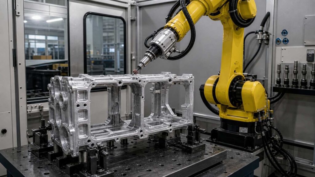
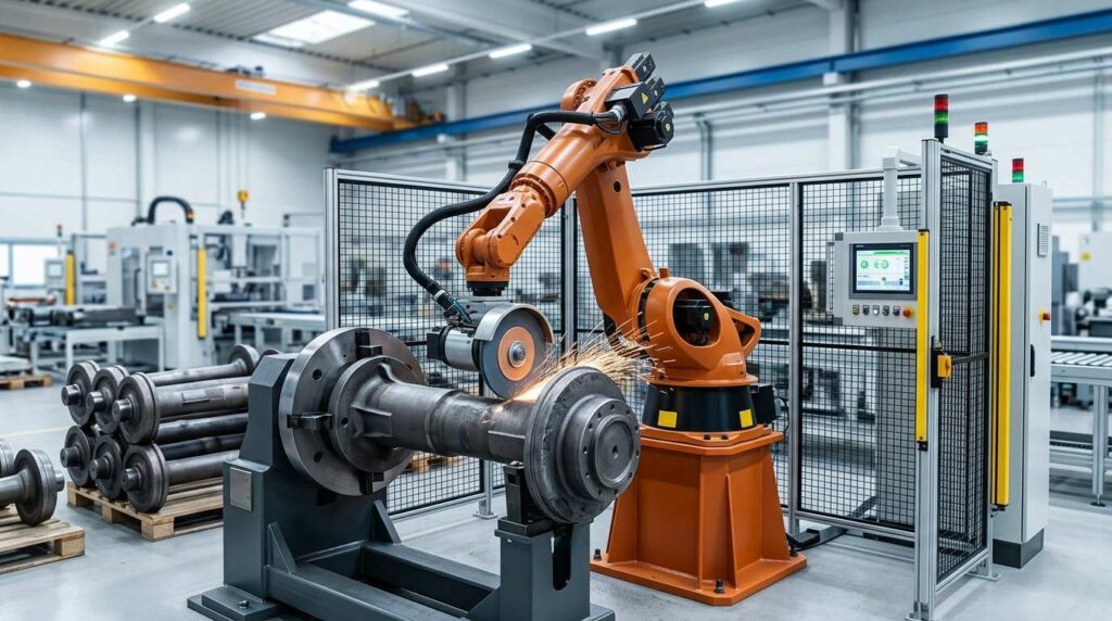
Cast iron valve bodies are medium and large flow-control castings used in industrial piping systems, fluid control equipment and mechanical installations. The workpiece usually has a central flow passage, curved outer contours, reinforced transition areas, connection ends and sealing-related surfaces, which makes post-casting finishing more difficult than simple structural castings.
This robotic grinding solution is designed for cast iron valve body workpieces with typical dimensions around 500 × 410 × 400 mm. It helps remove casting flash, burrs, parting lines and local surface defects from outer contours, opening edges and transition areas, while protecting sealing surfaces and critical connection faces.
What Is a Valve Body?
A valve body is the main structural casting of a valve. It forms the internal flow passage and provides the base for connections, sealing components and assembly interfaces. In industrial applications, valve bodies are widely used in piping systems, process control lines, fluid transport equipment and pressure-related mechanical systems.

For cast iron valve bodies, the casting usually includes a main flow channel, outer transition surfaces, reinforcement structures, end connection areas and local mounting features. After casting, these areas may contain flash, burrs, rough edges, residual gate marks and uneven surfaces. If they are not finished properly, the final part may face problems in assembly, coating quality, handling safety and dimensional consistency.
Unlike decorative parts, a valve body does not require mirror polishing in most cases. The main requirement is controlled grinding and deburring of casting defects while protecting sealing surfaces, connection faces and other functional areas.
| Item | Details |
|---|---|
| Workpiece Name | Cast Iron Valve Body |
| Chinese Name | 阀体 / 阀门阀体 |
| Typical Size | 500 × 410 × 400 mm |
| Material | Cast Iron |
| Main Process | Robotic Grinding |
| Assisted Processes | Deburring, Edge Rounding, Contour Finishing |
| Key Processing Areas | Outer contours, transition ribs, opening edges, parting lines, residual gate areas |
| Protected Areas | Sealing surfaces, connection faces, precision mounting areas |
| Finishing Goal | Remove flash, burrs and surface irregularities while protecting functional surfaces |
Typical Finishing Challenges of Cast Iron Valve Bodies
Cast iron valve bodies are more difficult to finish than simple flat or round castings because they combine curved outer contours, connection ends, transition areas and sealing-related surfaces in one workpiece. Some areas require flash removal and edge cleanup, while other areas must be protected from over-grinding.
For this type of casting, the main finishing difficulty comes from the combination of contour variation and functional-surface protection. Burrs and flash often remain around transition edges, opening boundaries and local corners, while sealing faces and connection regions require more careful process control during grinding and deburring.
| Common Problem | Specific Area | Impact |
|---|---|---|
| Casting Flash | Outer contour, parting lines, transition edges | Affects appearance and coating quality |
| Sharp Edges | Connection ends, rib boundaries, opening edges | Creates handling and assembly risks |
| Residual Burrs | Curved transitions, local corners, internal openings | Causes inconsistent finishing quality |
| Surface Irregularity | Outer curved surfaces and gate-cut regions | Reduces surface uniformity |
| Manual Variation | All contour grinding areas | Leads to unstable quality between operators |
| Sensitive Functional Areas | Sealing faces and connection regions | Risk of damage during manual grinding |
Robotic Grinding Process for Valve Body Castings
A robotic grinding cell for cast iron valve bodies should be designed around contour accessibility, fixture stability and functional-surface protection. The process must remove flash, burrs and parting lines from outer contours, opening edges and transition areas while avoiding damage to sealing surfaces and critical connection faces.
For valve body castings with typical dimensions around 500 × 410 × 400 mm, the process usually includes workpiece positioning, program selection, protected-area confirmation, contour grinding, edge deburring, transition finishing, inspection and unloading.
| Step | Process | Purpose | Tool / System |
|---|---|---|---|
| 1 | Loading and Positioning | Secure the valve body for stable access | Dedicated fixture |
| 2 | Program Selection | Match the correct part model and grinding path | HMI / Robot program |
| 3 | Protected Area Confirmation | Define sealing faces and no-grind zones | Fixture logic / Program setting |
| 4 | Outer Contour Grinding | Remove flash and parting lines on outer surfaces | Abrasive grinding tool |
| 5 | Edge Deburring | Smooth opening edges and local boundaries | Flexible deburring tool |
| 6 | Transition Area Finishing | Process rib roots and curved intersections | Small grinding head / Compliant tool |
| 7 | Quality Inspection | Check burr removal and protected surfaces | Manual or visual inspection |
| 8 | Unloading and Cleaning | Remove dust and send to next process | Air blow / Vacuum cleaning |
Step 1: Loading and Positioning
The valve body is placed into a dedicated fixture that supports the main body and stabilizes the connection ends. Because the workpiece has an irregular cast shape and medium-large size, accurate positioning is important for keeping the robot path consistent from part to part.
The fixture should provide stable support without blocking the grinding areas. For this valve body, the outer contours, transition sections and connection-end edges must remain accessible while sealing-related surfaces are protected from accidental contact.
Step 2: Program Selection
After the workpiece is fixed, the operator selects the corresponding robot program through the HMI. If several similar valve body models are produced in the same line, each model can have its own saved grinding path and tool sequence.
This step helps reduce operator dependence and prevents incorrect processing. For repeated production, the saved program allows the robot to process the same contour areas with consistent movement, tool angle and finishing logic.
Step 3: Protected Area Confirmation
Before grinding starts, the system must confirm which areas can be processed and which areas must be avoided. For valve body castings, sealing surfaces, connection faces and precision mounting areas should be treated as protected zones.
These no-grind areas can be controlled through robot path planning, fixture positioning or temporary shielding. This step is especially important because the goal is not only to remove casting defects, but also to protect the functional surfaces needed for later machining, sealing or assembly.
Step 4: Outer Contour Grinding
The robot first processes the main outer contour of the valve body, including the cylindrical body, curved outer surfaces, parting lines and accessible connection-end boundaries. This step removes major casting flash, surface protrusions and visible contour defects.
For cast iron valve bodies, outer contour grinding should not be overly aggressive. The robot should use a stable grinding path and suitable contact pressure to clean the casting surface while preserving the original geometry of the valve body.
Step 5: Edge Deburring
After the main contour is processed, the robot removes burrs from opening edges, connection-end transitions and local contour boundaries. These areas often contain sharp edges or small burrs left from casting and rough machining.
A flexible deburring tool or compliant abrasive tool is suitable for this step. The purpose is to smooth the edge and improve handling safety without cutting into protected sealing areas or changing the functional shape of the workpiece.
Step 6: Transition Area Finishing
Transition areas such as rib roots, curved intersections and local corners are usually more difficult to process than open surfaces. Burrs and flash can remain in these areas because the geometry changes quickly and manual grinding is hard to keep consistent.
The robot can use a smaller grinding head or flexible abrasive tool to finish these local areas. Proper path planning allows the tool to approach the transition zones from controlled angles, reducing missed burrs and improving contour consistency.
Step 7: Quality Inspection
After grinding and deburring, the valve body is inspected for remaining burrs, contour smoothness, over-grinding and protected-surface condition. Key inspection areas include outer contours, transition edges, opening boundaries, connection faces and sealing-related surfaces.

Inspection can be performed manually or with visual assistance depending on the production requirement. The main goal is to confirm that casting defects have been removed while functional areas remain undamaged.
Step 8: Unloading and Cleaning
The finished valve body is removed from the fixture and cleaned by air blowing, vacuum suction or brushing. Cast iron grinding dust can remain around openings, corners and transition areas, so cleaning is important before coating, machining or assembly.
For higher-volume production, unloading and cleaning can be integrated with conveyors, turntables or automatic handling systems. This helps reduce non-processing time and makes the robotic grinding cell more suitable for batch production.
Machining Difficulties and Solutions
| Challenge | Cause | Robotic Solution |
|---|---|---|
| Complex Curved Geometry | Mixed cylindrical body and curved transition surfaces | Multi-path programmed contour grinding |
| Burrs at Rib Roots and Edges | Casting flash accumulates at contour changes | Flexible deburring tools and local finishing paths |
| Functional Surface Protection | Sealing and connection faces must not be damaged | Protected zones excluded from grinding paths |
| Batch Variation | Flash thickness and local casting shape vary | Compliant tools and force-control strategy |
| Large Workpiece Handling | Medium-large casting is difficult to process manually | Stable fixture and repeatable robotic operation |
Difficulty 1: Complex Outer Contours
The valve body shown in the image has a non-flat geometry with multiple transitions. Manual grinding on these surfaces often creates uneven marks and inconsistent material removal.
The solution is to divide the robot path into several contour-processing regions. Each region can use a suitable tool angle and contact logic, giving more stable finishing on curved surfaces.
Difficulty 2: Local Burrs Around Transitions
Burrs often remain where curved surfaces meet ribs, edges or openings. These local transitions are easy to miss manually.
The solution is to add dedicated local finishing paths and use smaller abrasive heads or flexible deburring tools for corner access.
Difficulty 3: Sealing Surface Protection
Functional faces must remain undamaged. Random manual grinding near these areas is risky.
The solution is to define clear no-grind zones in the program and, if necessary, use fixture shielding or temporary protection for critical faces.
Difficulty 4: Inconsistent Casting Condition
Some valve body castings have thicker flash or rougher gate-removal areas than others. A fixed heavy-grinding method may remove too much material in some locations.
The solution is to use compliant tooling, controlled contact force and verified path margins so the robot can remove defects more consistently.
Manufacturing Case
Customer Background
A foundry and valve-component manufacturer produces medium and large cast iron valve body castings for industrial flow-control applications. The company previously relied on manual grinding to remove flash, burrs and rough contour defects after casting.
As output increased, the finishing process became difficult to standardize. The customer wanted to reduce manual workload, improve contour consistency and better protect sealing-related surfaces during finishing.
Technical Challenges
The valve body had a complex outer geometry with curved transitions, connection regions and localized burr-prone areas. Manual workers found it difficult to keep grinding quality consistent, especially around rib roots and contour edges. There was also concern about accidental damage to sealing or fitting faces.
Solution
A robotic grinding cell was configured with a six-axis industrial robot, dedicated valve-body fixture, abrasive grinding tool, flexible deburring tool and enclosed dust collection system. The process was divided into outer-contour grinding, local edge deburring and protected-area finishing logic.
| Item | Configuration |
|---|---|
| Workpiece | Cast Iron Valve Body |
| Typical Size | 500 × 410 × 400 mm |
| Main Process | Robotic Grinding |
| Assisted Process | Deburring and Contour Finishing |
| Robot | Six-Axis Industrial Robot |
| Tooling | Abrasive Grinding Tool, Flexible Deburring Tool |
| Fixture | Dedicated Valve Body Support Fixture |
| Protection Strategy | Sealing-face exclusion and protected-area logic |
| Dust Control | Enclosed Cell with Dust Collection |
Implementation Results
The robotic system improved consistency in outer-contour grinding and local burr removal. It also reduced heavy manual finishing work and lowered the risk of accidental grinding damage on functional surfaces.
| Result Area | Improvement |
|---|---|
| Contour Consistency | More stable finishing on curved outer surfaces |
| Burr Removal | Better repeatability at edges and transitions |
| Functional Surface Safety | Lower risk of damage to sealing-related areas |
| Labor Reduction | Reduced repetitive manual grinding workload |
| Production Stability | Saved programs for repeat valve body models |
| Workshop Environment | Cleaner grinding area with dust collection |
Customer Feedback
The customer reported that robotic grinding made the finishing process more stable for repeated valve body castings and helped balance burr removal efficiency with functional-surface protection.
FAQ
Q1: Is this workpiece a complete valve or a valve body casting?
Based on the shape and the finishing requirement, it should be treated as a valve body casting rather than a complete assembled valve.
Q2: Why is robotic grinding suitable for this valve body?
Because the part has complex outer contours, repeated transition areas and burr-prone edges that are difficult to process consistently by hand.
Q3: What areas can the robot process?
The robot can process outer contours, edge transitions, local burr areas, parting lines and residual gate-removal zones, while avoiding protected sealing faces.
Q4: Does this part need polishing?
In most cases, no mirror polishing is required. The main need is grinding, deburring and contour finishing for casting cleanup and surface preparation.
Q5: How are sealing surfaces protected?
They can be excluded through programmed no-grind zones, fixture shielding and inspection control.
Q6: Can one cell handle similar valve body models?
Yes. If the product family is similar, separate programs and suitable fixtures can allow one cell to process multiple related models.
Conclusion
Cast iron valve bodies have complex outer contours, transition areas and sealing-related surfaces, making manual grinding difficult to standardize. A robotic grinding solution helps manufacturers remove flash, burrs and parting lines more consistently while protecting critical functional areas.
If your valve body production still relies on manual contour grinding, flash removal or local burr cleanup, Contact Us for a customized robotic solution. You can also explore our General Metal applications and Equipment to learn more about our robotic finishing systems.