
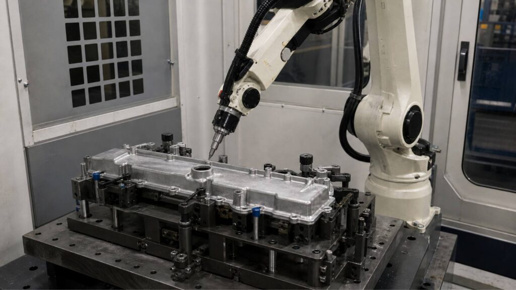
Aluminum alloy engine cylinder head covers are thin-wall cover castings used on the upper section of automotive engines. Based on typical sample workpieces, this part includes a broad cover body, perimeter sealing edge, bolt holes, raised bosses, reinforced ribs, breather-related structures and local recessed areas, making post-casting deburring more complex than simple flat aluminum covers.
This robotic deburring solution is designed for aluminum alloy engine cylinder head covers with typical dimensions around 350–650 mm in length, depending on the engine model. It helps remove burrs, light flash, sharp edges and trimming residues from the outer perimeter, sealing-adjacent edges, bolt holes, ribs, bosses and local openings while improving edge consistency and reducing manual deburring workload.
What Is an Aluminum Alloy Engine Cylinder Head Cover?
An aluminum alloy engine cylinder head cover, also known as a valve cover or rocker cover in some applications, is a cover-type component mounted above the engine cylinder head. Its main function is to cover the valve train area, help seal engine oil, protect internal components from dust and support related ventilation or oil separation structures.
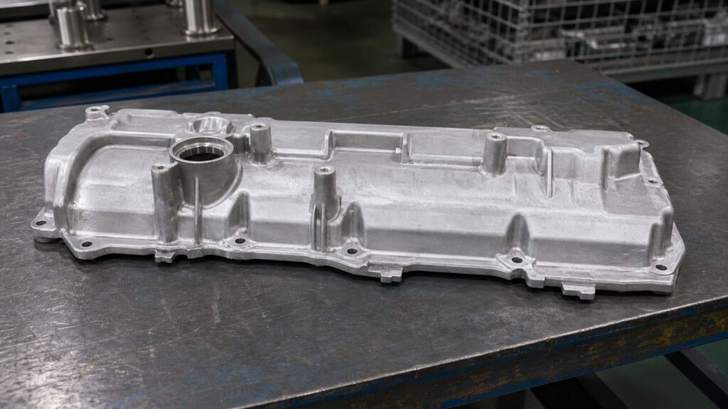
Based on typical workpiece features, this part usually has a thin-wall shell structure, long perimeter edges, sealing grooves or sealing-adjacent boundaries, multiple bolt holes, raised bosses, reinforcing ribs and local vent or oil-return openings. After casting and trimming, burrs, flash or sharp edges may remain around the outer contour, screw holes, ribs, bosses, breather openings and sealing-edge boundaries. For this type of workpiece, the main finishing requirement is robotic deburring, edge rounding and local cleanup rather than heavy grinding or decorative polishing.
| Item | Details |
|---|---|
| Workpiece Name | Aluminum Alloy Engine Cylinder Head Cover |
| Chinese Name | 铝合金发动机缸盖罩 |
| Alternative Name | Aluminum Alloy Valve Cover / Rocker Cover |
| Typical Size | Around 350–650 × 180–350 × 60–150 mm, depending on model |
| Material | Aluminum Alloy Casting |
| Main Process | Robotic Deburring |
| Assisted Processes | Edge Rounding, Light Flash Removal, Local Surface Cleanup |
| Key Processing Areas | Outer perimeter, sealing-adjacent edges, bolt holes, raised bosses, ribs, breather openings, local recessed areas |
| Protected Areas | Sealing grooves, gasket contact surfaces, mounting faces, precision holes, thin-wall edges |
| Finishing Goal | Remove burrs, light flash and sharp edges while protecting sealing and thin-wall structures |
Typical Finishing Challenges of Aluminum Alloy Engine Cylinder Head Cover
An aluminum alloy engine cylinder head cover is different from heavy structural castings because its wall thickness is relatively thin and many burrs are distributed around long edge boundaries, sealing-adjacent areas and small holes. The workpiece may deform or show visible tool marks if excessive pressure is applied during manual deburring.
Manual deburring can be inconsistent around the perimeter sealing edge, bolt holes, ribs and vent openings. Some operators may over-round thin edges, while others may leave small burrs near the sealing groove or boss transitions. Since the part is a cover component, stable edge quality and sealing-area protection are more important than aggressive stock removal.
| Common Problem | Specific Area | Impact |
|---|---|---|
| Light Casting Flash | Outer perimeter, cover edge, local trimming areas | Affects appearance and edge consistency |
| Sharp Edges | Perimeter edges, bolt holes, vent openings | Creates handling and assembly risks |
| Residual Burrs | Rib roots, boss boundaries, recessed areas | Causes unstable finishing quality |
| Sealing-Edge Burrs | Sealing-adjacent boundaries and gasket areas | May affect assembly preparation or sealing reliability |
| Manual Variation | Long edges, repeated bolt holes and ribs | Leads to inconsistent results between operators |
| Thin-Wall Sensitivity | Cover body, raised edges and local corners | Risk of deformation, over-rounding or tool marks |
Robotic Deburring Process for Aluminum Alloy Engine Cylinder Head Cover
A robotic deburring cell for aluminum alloy engine cylinder head covers should be designed around light contact force, stable fixture support, edge tracking and sealing-area protection. The process must remove burrs and sharp edges from the cover perimeter, holes, ribs and local openings while avoiding damage to sealing grooves, gasket contact surfaces and thin-wall features.

For engine cylinder head covers with typical dimensions around 350–650 mm in length, the process usually includes loading, program selection, protected-area confirmation, perimeter deburring, bolt hole treatment, rib and boss cleanup, vent opening deburring, inspection and unloading. Flexible deburring tools, chamfering tools and small finishing heads can be selected according to the actual burr type and cover geometry.
| Step | Process | Purpose | Tool / System |
|---|---|---|---|
| 1 | Loading and Positioning | Secure the thin-wall cover for stable deburring | Dedicated support fixture |
| 2 | Program Selection | Match the correct cover model and edge path | HMI / Robot program |
| 3 | Protected Area Confirmation | Define sealing and thin-wall no-touch zones | Fixture logic / Program setting |
| 4 | Outer Perimeter Deburring | Remove sharp edges and light flash from the cover contour | Flexible deburring tool |
| 5 | Sealing-Adjacent Edge Control | Clean burrs near sealing boundaries without touching gasket surfaces | Controlled robotic path |
| 6 | Bolt Hole and Boss Edge Treatment | Deburr mounting holes and raised boss boundaries | Chamfering tool / Deburring spindle |
| 7 | Rib and Local Opening Cleanup | Process rib roots, vent openings and recessed features | Small finishing head / Compliant tool |
| 8 | Quality Inspection | Check edge condition and protected sealing areas | Manual or visual inspection |
| 9 | Unloading and Cleaning | Remove chips and transfer the cover | Air blow / Vacuum cleaning |
Step 1: Loading and Positioning
The aluminum alloy engine cylinder head cover is loaded into a dedicated support fixture. Because the part is a thin-wall cover casting, the fixture should support the workpiece across stable non-critical areas instead of clamping only one narrow edge.
Stable positioning helps prevent vibration and deformation during robotic deburring. The fixture should also provide enough access for the robot to reach the outer contour, bolt holes, sealing-adjacent edges, ribs and local openings.
Step 2: Program Selection
After the cover is fixed, the operator selects the correct robot program through the HMI. This is useful when one robotic cell handles different engine cover models with different hole positions, rib layouts or sealing-edge paths.
The selected program defines the deburring sequence, tool angle, feed speed, contact pressure and protected zones. Saved programs help maintain consistent results for repeated production batches.
Step 3: Protected Area Confirmation
Before deburring starts, the system confirms which areas must remain untouched. For an engine cylinder head cover, protected areas usually include sealing grooves, gasket contact surfaces, mounting faces, precision holes and thin-wall edges that are easy to deform.
This step is critical because burr-prone edges may be very close to sealing areas. The robot should remove burrs from the edge boundary while keeping the tool away from surfaces that affect sealing performance.
Step 4: Outer Perimeter Deburring
The outer perimeter is one of the main burr areas on an engine cylinder head cover. Light flash, trimming marks and sharp edges may remain along the long cover contour after casting or rough cleanup.
A flexible deburring tool can follow the outer profile with controlled contact pressure. The goal is to remove sharp edges and make the perimeter safer to handle without changing the cover shape or removing too much aluminum material.
Step 5: Sealing-Adjacent Edge Control
The sealing-adjacent area requires more careful processing than ordinary edges. Burrs near the gasket boundary must be removed, but the sealing groove or gasket contact surface must not be scratched or over-ground.
The robot uses controlled tool posture and no-touch zones to process only the edge boundary. This helps maintain sealing reliability while improving burr removal consistency around the cover.
Step 6: Bolt Hole and Boss Edge Treatment
Engine cylinder head covers usually include many bolt holes and raised bosses. Burrs around these features may affect screw assembly, bolt seating or part handling.
A chamfering tool or deburring spindle can process each hole opening with repeatable depth and angle. The robot can also follow local boss boundaries to remove small burrs without damaging the raised functional structure.
Step 7: Rib and Local Opening Cleanup
Ribs, vent openings, oil-return openings or local recessed areas may retain small burrs after casting. These areas are easy to miss during manual processing because they are smaller and require frequent tool angle changes.
A small finishing head or compliant deburring tool can clean these local features with stable posture. The robot can divide the cover into several processing zones and remove residual burrs from ribs, openings and recessed transitions.
Step 8: Quality Inspection
After robotic deburring, operators inspect the outer perimeter, bolt holes, boss boundaries, sealing-adjacent edges, ribs and local openings. The inspection confirms that burrs and sharp edges have been removed and that sealing surfaces remain undamaged.

Visual inspection can be combined with manual touch checks or sample inspection tools depending on production requirements. Inspection feedback can also be used to optimize tool wear compensation and local path adjustment.
Step 9: Unloading and Cleaning
After inspection, the engine cylinder head cover is unloaded and transferred to the next process. Aluminum chips and fine particles should be removed from bolt holes, ribs, recessed areas and sealing-adjacent boundaries.
An enclosed robotic cell with chip and dust collection is recommended for aluminum alloy deburring. It helps keep the finishing area cleaner and reduces the operator’s direct exposure to repetitive manual deburring work.
Machining Difficulties and Solutions
| Challenge | Cause | Robotic Solution |
|---|---|---|
| Thin-Wall Cover Deformation | The cover body is lighter and thinner than structural castings | Dedicated support fixture and controlled contact force |
| Long Perimeter Burrs | Large cover outline creates long edge paths | Programmed perimeter deburring path |
| Sealing Edge Protection | Burrs are close to gasket or sealing surfaces | No-touch zones and controlled tool angle |
| Repeated Bolt Hole Burrs | Multiple mounting holes require consistent edge treatment | Chamfering or robotic deburring routine |
| Rib and Vent Opening Burrs | Small local features create hidden burrs | Small tool access with local finishing paths |
| Aluminum Surface Marks | Soft aluminum can be marked by excessive pressure | Flexible tooling and optimized feed speed |
Difficulty 1: Thin-Wall Cover Stability
The engine cylinder head cover is usually lighter and thinner than an engine cylinder head or lower frame casting. If the fixture support is not stable, the cover may vibrate during deburring and cause uneven edge quality.
The solution is to use a dedicated support fixture and controlled contact force. This allows the robot to remove burrs from long edges and local features while reducing the risk of deformation or chatter marks.
Difficulty 2: Sealing-Adjacent Edge Deburring
The cover has sealing-adjacent boundaries that are close to gasket contact surfaces or sealing grooves. These areas must be deburred carefully because scratches or over-removal may affect sealing performance.
The solution is to define sealing surfaces as protected zones. The robot processes only the nearby edge and avoids direct tool contact with the sealing groove or gasket surface.
Difficulty 3: Repeated Bolt Hole and Boss Burrs
Multiple bolt holes and raised bosses create repeated burr locations across the cover. Manual deburring may produce inconsistent chamfer depth and uneven hole edge quality.
The solution is to use a robotic hole-edge routine with a chamfering tool or deburring spindle. The robot approaches each hole with consistent angle and depth, improving repeatability across all mounting points.
Difficulty 4: Local Rib and Breather Opening Cleanup
Ribs, breather openings and small recessed features may contain residual burrs that are easy to miss by hand. These features are often located on different surfaces and require changing tool posture.
The solution is to use a small finishing tool and divide the cover into local processing zones. The robot can reach each feature with repeatable posture and remove small burrs more consistently.
Manufacturing Case
Customer Background
An automotive aluminum casting manufacturer produces engine cylinder head covers for passenger vehicle engine assemblies. Before automation, operators manually removed burrs, light flash and sharp edges from cover perimeters, bolt holes, bosses, ribs and sealing-adjacent areas.
As production volume increased, manual deburring became difficult to standardize. Some long perimeter edges remained sharp, while some sealing-adjacent areas were at risk of tool marks. The customer wanted to improve edge consistency, reduce manual workload and protect sealing surfaces more reliably.
Technical Challenges
The workpiece had a thin-wall cover structure with long perimeter edges, multiple bolt holes, raised bosses, ribs and local openings. Most defects were light burrs and sharp edges rather than heavy casting residues.
The main challenge was controlled deburring. The robotic process needed to clean edges consistently while avoiding deformation, over-rounding and accidental contact with sealing grooves or gasket surfaces.
Solution
The proposed solution used a six-axis industrial robot, a dedicated cover support fixture and an edge-focused deburring tool system. A flexible deburring tool was used for the outer perimeter, a chamfering tool was used for bolt holes, and a small finishing head was used for ribs, bosses and local openings.
Sealing grooves, gasket contact surfaces, mounting faces and precision holes were defined as no-touch zones. The robot processed only the edge boundaries using controlled tool angle and light contact pressure. The enclosed cell included aluminum chip and dust collection for cleaner production.
| Item | Configuration |
|---|---|
| Workpiece | Aluminum Alloy Engine Cylinder Head Cover |
| Chinese Name | 铝合金发动机缸盖罩 |
| Typical Size | Around 350–650 × 180–350 × 60–150 mm, depending on model |
| Main Process | Robotic Deburring |
| Assisted Process | Edge Rounding, Light Flash Removal, Local Surface Cleanup |
| Robot | Six-Axis Industrial Robot |
| Tooling | Flexible deburring tool, chamfering tool, small finishing head |
| Fixture | Dedicated Thin-Wall Cover Support Fixture |
| Protection Strategy | Protected sealing grooves, gasket surfaces, mounting faces and precision holes |
| Dust Control | Enclosed Cell with Aluminum Chip and Dust Collection |
Implementation Results
The robotic cell took over repetitive deburring work on the outer perimeter, bolt holes, boss edges, ribs, local openings and sealing-adjacent boundaries. Operators mainly handled loading, unloading, inspection and tool maintenance, which reduced repetitive manual deburring intensity and improved repeated batch stability.
The process also reduced the risk of over-processing near sealing areas. Instead of relying on manual pressure control, the robot followed saved paths with controlled contact force, helping maintain stable edge quality across different cover batches.
| Result Area | Improvement |
|---|---|
| Perimeter Edge Quality | More consistent edge cleanup along the cover outline |
| Bolt Hole Deburring | Repeatable burr removal around mounting holes |
| Sealing-Area Protection | Lower risk of scratches on sealing grooves and gasket surfaces |
| Rib and Opening Cleanup | Reduced missed burrs on local cover features |
| Thin-Wall Protection | Lower risk of deformation and over-rounding |
| Labor Reduction | Reduced repetitive manual deburring workload |
| Production Stability | Saved programs for repeated cover models |
| Workshop Environment | Cleaner finishing area with enclosed aluminum chip collection |
Customer Feedback
The customer reported that the robotic deburring cell made repeated engine cylinder head cover finishing more stable and reduced the manual effort required for perimeter cleanup, bolt hole deburring and sealing-adjacent edge control. Operators could focus more on part handling, inspection and tool monitoring instead of continuous manual deburring.
Information Needed for a Robotic Grinding Proposal
To recommend a suitable robotic deburring cell for your aluminum alloy engine cylinder head cover, we usually need the part drawing, material grade, casting weight, photos of burrs, flash or sharp edges, required deburring areas, protected sealing surfaces, current manual deburring cycle time and annual production volume.
These details help our engineering team evaluate fixture design, robot reach, tool selection, chip collection layout and process feasibility. For thin-wall aluminum cover castings, it is especially important to identify which edges require deburring and which sealing grooves, gasket surfaces or precision holes must be protected during robotic processing.
FAQ
Q1: Is an engine cylinder head cover the same as an engine cylinder head?
No. An engine cylinder head cover is a cover component mounted above the cylinder head, while the engine cylinder head is a core engine structural part. The cover mainly requires edge deburring and sealing-area protection, while the cylinder head usually involves more complex hole, chamber and passage edge cleanup.
Q2: Why is robotic deburring suitable for engine cylinder head covers?
Robotic deburring is suitable because the cover has repeated perimeter edges, bolt holes, ribs, bosses and sealing-adjacent boundaries. A robot can follow programmed paths with stable contact force, improving consistency compared with manual deburring.
Q3: What areas can the robot process on a cylinder head cover?
The robot can process the outer perimeter, bolt hole edges, boss boundaries, rib roots, breather openings, oil-return openings and sealing-adjacent edges. The exact processing range should be confirmed according to the drawing and actual burr distribution.
Q4: Does this part require polishing?
In most cases, this part does not require decorative polishing. The main requirement is deburring, edge rounding, light flash removal and local cleanup.
Q5: How are sealing surfaces protected during deburring?
Sealing surfaces are protected through fixture positioning, robot path planning and no-touch zones. The robot processes only the edge boundary and avoids direct contact with gasket surfaces or sealing grooves.
Q6: Can one robotic cell handle different cylinder head cover models?
Yes. One robotic cell can often handle different cover models if the fixture, robot reach and tool system are designed for model variation. Different robot programs can be saved for different part numbers.
Conclusion
Aluminum alloy engine cylinder head covers have thin-wall structures, long perimeter edges, bolt holes, bosses, ribs and sealing-adjacent boundaries, making manual deburring difficult to standardize. A robotic deburring solution helps manufacturers remove burrs, light flash and sharp edges while improving edge consistency and protecting sealing surfaces.
If your engine cylinder head cover production still relies on manual perimeter deburring, bolt hole cleanup or sealing-edge treatment, Contact Us for a customized robotic solution. You can also explore our Automotive & EV applications and Equipment to learn more about our robotic finishing systems.

