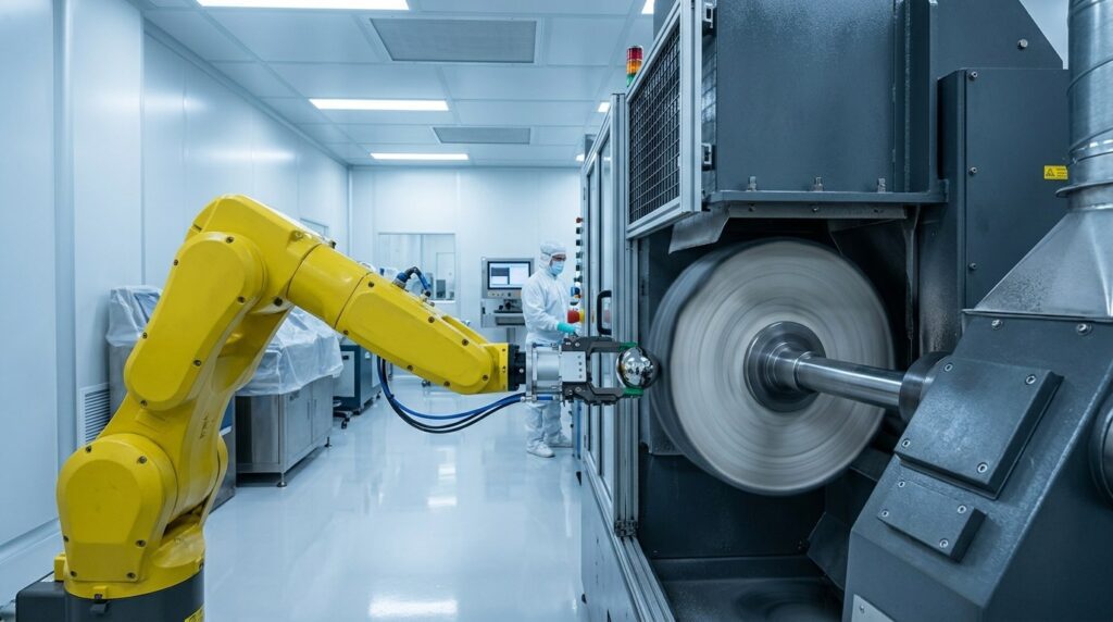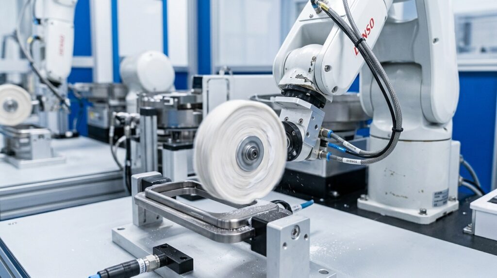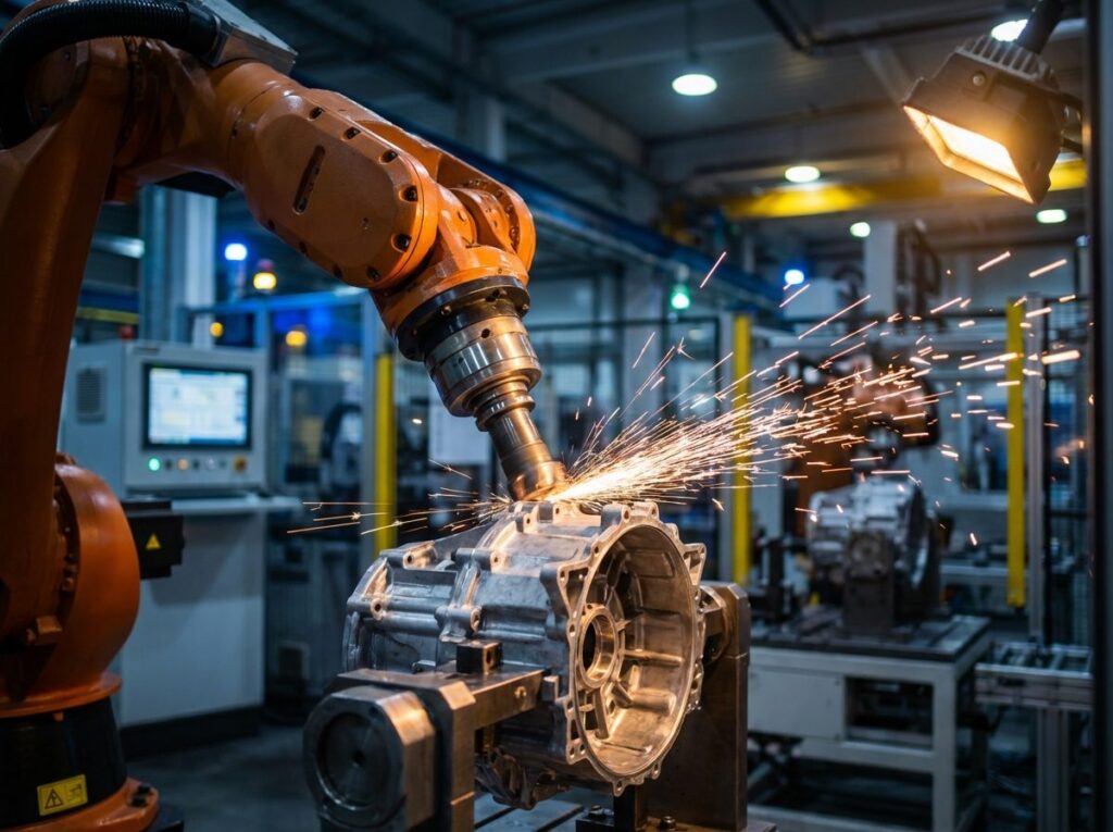
The quality of deflashing and edge deburring directly impacts the sealing performance and overall assembly of aluminum die-cast motor housings. Starting from real shop-floor pain points, this article breaks down the core technologies behind automated motor housing deburring. We cover process comparisons (manual vs. robotic), the application of active force control technology, process flow breakdown, and consumable cost control. Through detailed technical data and actual production cases, we demonstrate the economic benefits of automated grinding solutions, helping you solve flash challenges and achieve optimal balance between quality and efficiency.
What is a Die-Cast Motor Housing?
The aluminum die-cast motor housing is a critical component in the powertrain of New Energy Vehicles (NEVs). It primarily protects the internal stator and rotor while providing water channels for heat dissipation and structural mounting support. According to NEV industry standards, the specifications vary greatly, and the requirements for the flatness of mating surfaces and the precision of sealing grooves are extremely strict.
Application Scenarios
Aluminum die-cast motor housings are primarily used in the powertrains of NEVs and heavy industrial equipment. Depending on the application:
- Battery Electric Vehicle (BEV) Drive Motors: Extremely high sealing requirements for the water jacket. Over-cutting or missing burrs on the flange mating surface is strictly prohibited.
- Hybrid Electric Vehicle (HEV) Integrated Transmission Housings: Complex internal oil channels where cross-hole burrs are extremely difficult to clean.
- Industrial Servo Motors: Requires excellent cosmetic consistency with no visible grinding chatter marks.
All applications require strict assembly precision, as incomplete deburring or over-grinding on mating surfaces can lead to oil/water leaks or even motor short circuits—a risk pattern shared across general metal part manufacturing.
Structural Characteristics
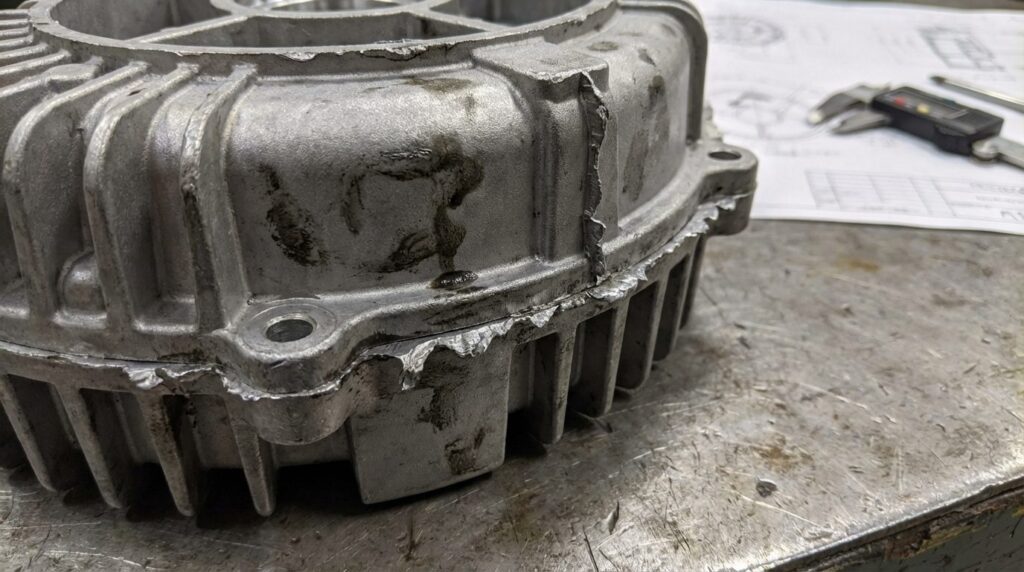
- Complex Parting Lines: The seams of the die-casting mold create flash of uneven thickness and high hardness.
- Dense Cooling Fins & Deep Holes: The exterior is covered with cooling structures, while the interior has numerous tapped holes and intersecting oil channels.
- Thin-Walled Structures Prone to Deformation: Localized thin walls can easily deform under aggressive manual grinding forces.
- Material: Cast aluminum alloys like ADC12 or A380 offer good fluidity and heat dissipation but are prone to sticking to cutting tools.
- Surface Quality: High roughness requirements for flange mating surfaces to ensure seamless gasket assembly.
Key Characteristics of Motor Housing Machining
Key Characteristics:
- High Consistency: Flatness error on mating surfaces must be controlled within a microscopic range.
- High Efficiency: Must meet the high-volume, fast-cycle production demands of the automotive industry.
- Cleanliness Requirements: Internal oil/water channels must leave no residual aluminum chips or burrs behind.
Technical Parameters for Deburring Motor Housings
| Item | Parameter Range | Notes |
| Flash Thickness Capacity | 0.5mm – 5.0mm | Varies with die-casting machine tonnage and mold wear |
| Chamfer/Radius Size | R0.5 – R2.0 | Set according to drawing requirements |
| Mating Surface Protection | Over-cut < 0.05mm | Guaranteed by active force control technology |
| Post-Grinding Roughness | Ra1.6 – Ra3.2 | Meets sealing gasket assembly requirements |
| Production Cycle Time | 2 – 4 Minutes | Depends on housing complexity |
Why is Robotic Deburring Preferred for Motor Housings?
Conventional Manual Grinding Pain Points
When using conventional manual angle grinders or pneumatic files, factories face the following challenges:
| Pain Point | Specific Issue | Impact |
| Extremely Poor Consistency | Workers’ varying pressure due to fatigue easily causes over-cutting (gouging) on flange surfaces. | Leads to water/oil leaks after assembly, causing entire batch rejections. |
| Labor Shortages & High Injury Risk | Heavy dust, high noise, and explosion risks associated with aluminum powder in die-casting plants. | Young workers refuse this job, leading to severe labor shortages. |
| Low Efficiency | Internal cross-holes require frequent tool changes by hand. | Slow cycle times cannot match the high output of die-casting machines, causing bottlenecks. |
Advantages of Robotic Automation
Robotic deburring cells—built on the principles we cover in what is robotic deburring—offer a systematic answer to these pain points:
| Comparison Dimension | Manual Grinding | Robotic Deburring | Improvement |
| Machining Efficiency | 12-15 min/piece | 2.5-3.5 min/piece | Cycle time cut several-fold |
| Defect Rate (Over-cut) | Frequent over-cut scrap | Rare with force control | Massive reduction in scrap |
| Surface Precision | Relies on worker feel | Constant force floating | Removes operator variability |
| Consumable Life | Fast depletion | Uniform tool wear | Steadily lower tool spend |
Core Advantages:
- Active Force Control: The deburring spindle features radial/axial compliance. Acting like a car’s suspension, it automatically adapts to slight dimensional variations in the rough casting, maintaining constant pressure and never gouging the base material.
- Multi-Process Integration: With an Automatic Tool Changer (ATC), a single setup completes heavy deflashing, edge radiusing, and internal hole brushing.
- 24/7 Operation: Unaffected by dust or fatigue, enabling lights-out manufacturing to meet strict automotive delivery schedules.
Automated Deburring Process Workflow
From vision-guided loading to final blue-light inspection, the surface treatment of an aluminum motor housing runs through eight automated steps, with the robotic grinding concentrated in steps 02-05.
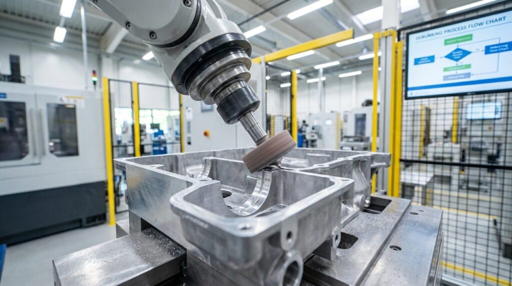
Complete Process Flow
| Process | Process Name | Equipment/Tool | Consumable | Time | Precision Control |
| 01 | Vision-Guided Loading | 3D Vision + Robot | – | 15s | Recognition ±0.5mm |
| 02 | Heavy Deflashing | High-Rigidity Spindle | Carbide Rotary Burr | 45s | Removes flash >2mm |
| 03 | Flange Blending | Floating Spindle | Flap Wheel/Nylon | 60s | Prevents over-cutting |
| 04 | Flexible Edge Radiusing | Radial Compliant Tool | Special Chamfer Insert | 40s | Uniform R-corner transition |
| 05 | Cross-hole Cleaning | Flexible Spindle | Deburring Tube Brush | 35s | Cleans chips from blind holes |
| 06 | High-Pressure Wash | Industrial Washer | Detergent | 60s | Meets industry cleanliness specs |
| 07 | Air Blow Drying | Air Knife | – | 30s | No water spots |
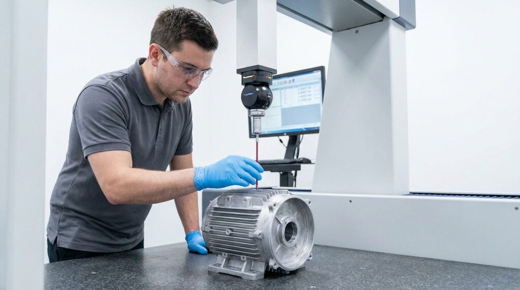
| 08 | Inspection | 3D Blue Light Scanner | – | 20s | Full dimensional & burr check |
Process Descriptions
Step 1: Vision-Guided Loading
Purpose: Identify randomly piled rough castings in a bin, guiding the robot to grip and place them precisely on the grinding positioner.
Key Points: Utilize anti-reflective 3D vision technology to handle the shiny aluminum surface.
Step 2: Heavy Deflashing
Purpose: Quickly remove thick, hard aluminum flash at the parting lines.
Key Points: Requires a highly rigid robotic system and high-power electro-spindle with carbide burrs. Optimized toolpaths prevent tool jamming.
Step 3: Flange Blending
Purpose: Clean micro-burrs on critical mating surfaces without compromising flatness.
Key Points: This is the most critical step. An axial floating spindle is required. Set to a constant pressure (e.g., 20N), the abrasive wheel perfectly follows the surface regardless of minor casting undulations—removing the burr without touching the base metal.
Step 4: Flexible Edge Radiusing
Purpose: Eliminate sharp edges and create uniform radii or chamfers.
Key Points: Using a radial floating spindle, pneumatic or spring mechanisms provide flexibility. The robot follows a rough contour path, and the floating head automatically compensates for casting tolerances.
Step 5: Internal/Cross-hole Cleaning
Purpose: Remove hidden burrs inside oil and water channels to prevent future detachment.
Key Points: The spindle automatically swaps to an abrasive nylon brush, feeding in a spiral motion to clean blind cavities.
Step 6: High-Pressure Wash
Purpose: Thoroughly wash away adhering aluminum chips, dust, and cutting fluid from the surface.
Step 7: Air Blow Drying
Purpose: Rapidly remove moisture to prevent oxidation and water spots on the cast aluminum surface.
Step 8: Inspection
Purpose: Inspect the grinding quality to ensure there are no missed deburring areas or over-cutting.
Machining Challenges & Solutions
Challenge 1: Inconsistent Casting Dimensions (Deformation)
Problem:
- Castings from the same batch can vary by 1-2mm due to cooling shrinkage.
- A rigid robot following a fixed path will over-cut (scrap) larger parts and under-cut smaller ones.
Solution:
- Implement Active Compliant Technology.
- Install a floating deburring head with force sensors. It automatically extends or retracts to compensate for the 1-2mm variance while maintaining a constant cutting force.
- Result: Over-cut scrap caused by casting-to-casting dimensional mismatch becomes rare instead of routine.
Challenge 2: Deburring Intersecting Deep Oil Channels
Problem:
- Root burrs form at the intersections of internal cooling channels.
- Conventional tools cannot reach inside complex, curved cavities.
Solution:
- Utilize custom non-standard Abrasive Nylon Brushes or High-Pressure Waterjet Deburring.
- Result: Meets the strict particulate cleanliness standards of the automotive industry, preventing hydraulic jamming in the motor.
Application Scenario
Project Profile
Project profile: a Tier 1 automotive parts supplier in Southeast Asia, die-casting motor housings for global NEV programs.
Technical Challenges
- Ran a manual grinding line of roughly a dozen stations in heavy dust, with constant operator turnover.
- Flange grinding quality relied entirely on worker feel, leading to high rework rates due to leaks.
- Client required cycle times to be compressed to 3 minutes/piece.
The Solution
| Item | Configuration |
| Workpiece | NEV Drive Motor Aluminum Housing |
| Material | ADC12 Aluminum Alloy |
| Equipment | 6-Axis Rigid Robot + External Positioner |
| Core Tool | Radial/Axial Active Compliant Spindle System |
| Process | Vision Load -> Heavy Deflashing -> Flange Blend -> Cavity Brush |
| Cycle Time | 2.5 Minutes / Piece |
Implementation Results
- Labor: A single robotic cell absorbs the workload of several skilled manual grinding stations per shift and sustains three-shift production.
- Quality: Flange over-cut scrap from uneven hand pressure largely disappears, and mating-surface leak tests settle into a stable, repeatable pass pattern.
- Environment: Equipped with wet dust extraction, eliminating dust pollution and explosion hazards.
- ROI: Once labor, scrap and rework savings are counted, systems of this class typically pay back within one to two years.
FAQ
Q1: How thick of a flash can the robot handle?
A: Our heavy-duty spindles with carbide burrs easily handle solid aluminum flash 3mm-5mm thick. For thicker overflow wells or gates, we recommend automated band sawing or trimming presses prior to robotic fine grinding to save consumable costs.
Q2: Does the floating head really prevent over-cutting the flange?
A: Yes, this is the core value of floating technology. By using pneumatic or servo control to maintain constant contact force, the tool automatically retracts if the casting is slightly oversized or the robot path deviates, ensuring the base material is never gouged.
Q3: Aluminum sticks to tools easily. How are consumable costs controlled?
A: We recommend special coated, large-flute aluminum-specific burrs and anti-clogging flap wheels. Combined with optimized spindle speeds and micro-lubrication (MQL), tool life is significantly extended, typically reducing consumable costs by over 30% compared to manual grinding.
Q4: How long does it take to change over to a different motor housing model?
A: Our cells feature quick-change fixtures and parametric programming. Operators simply swap the locating fixture and select the pre-saved robot program on the HMI. With practice, a complete changeover takes 15-30 minutes, ideal for high-mix, low-volume flexible production.
Conclusion
The deflashing and deburring of aluminum die-cast motor housings using robotic automated floating grinding processes removes the human variable from the process. With cycle times of 2.5-3.5 minutes per piece, it has become the practical standard for meeting the volume and quality demands of the NEV industry. The same heavy-payload architecture also serves other large aluminum castings—see our aluminum chair base polishing solution.
Thick flash, leak-prone flange grinding and a hazardous dust environment are all problems a well-configured robotic cell addresses directly. Send us your motor housing drawings—the engineering team will run sample parts and build an ROI case for your line.