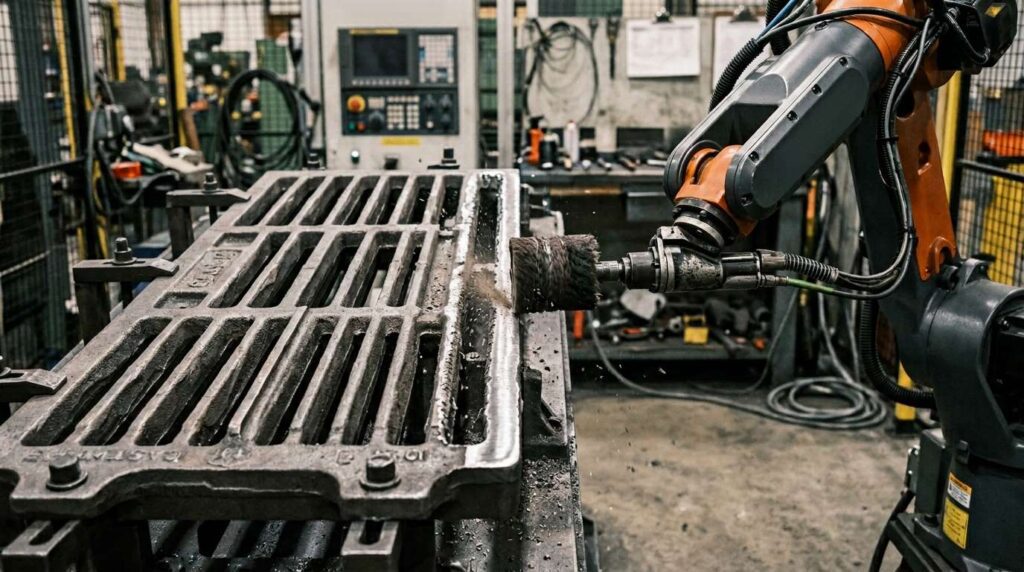
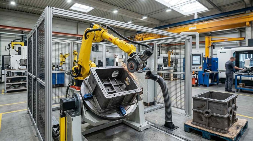
Cast iron brake backing plates are structural brake components used in braking systems where support, positioning and assembly stability are required. This part typically includes a large central opening, stepped outer contours, local bosses, mounting features and multiple edge transitions, making post-casting finishing more difficult than on simple flat castings.
This robotic grinding solution is designed for cast iron brake backing plate castings, which are typically 300–450 mm across depending on the brake design. It helps remove burrs, process hole edges, clean contour transitions and improve finishing consistency while reducing manual grinding workload.
What Is a Brake Backing Plate?
A brake backing plate is a structural brake component used to support, position or connect related brake-system parts. This workpiece is a cast iron backing-plate-type part with a central bore, stepped outer contour, local mounting features and several edge and opening areas that require post-casting cleanup.

After casting and rough machining, burrs, flash and sharp edges may remain around the central opening, outer profile, mounting edges and local transition zones. For this type of workpiece, the main finishing requirement is not decorative polishing, but robotic grinding, deburring and hole-edge treatment while protecting important fitting and mounting areas. If these process terms are new to you, our introduction to robotic deburring explains the basic categories.
| Artículo | Detalles |
|---|---|
| Nombre de la pieza | Cast Iron Brake Backing Plate |
| Tamaño habitual | Around 300–450 mm across, depending on brake design |
| Material | Hierro fundido |
| Proceso principal | Rectificado robotizado |
| Procesos asistidos | Deburring, Edge Rounding, Hole Edge Treatment |
| Áreas clave de procesamiento | Outer contour edges, central opening, hole boundaries, local bosses, parting lines |
| Áreas protegidas | Fitting faces, mounting interfaces, precision contact areas |
| Gol de la victoria | Remove burrs, smooth edges and improve finishing consistency |
Typical Finishing Challenges of Cast Iron Brake Backing Plates
Cast iron brake backing plates are more difficult to finish than ordinary plate-like castings because the workpiece combines a large central opening, stepped outer contour, raised features and local mounting areas in one compact structure. Burrs and flash may remain around the opening edge, contour boundaries and feature transitions after casting.
Another challenge is finishing consistency. Manual grinding on this type of part often produces uneven edge quality, especially around stepped contours, local bosses and recessed transition areas. If burrs remain near the hole edges or fitting zones, they may affect later assembly and part quality.
| Problema habitual | Área específica | Impacto |
|---|---|---|
| Flash de fundición | Outer contour and parting lines | Affects appearance and edge consistency |
| Bordes afilados | Opening boundaries, outer edges and feature corners | Genera riesgos en la manipulación y el montaje |
| Rebabas residuales | Hole edges, bosses and local transitions | Provoca una calidad de acabado inestable |
| Surface Irregularity | Stepped faces and contour transitions | Reduce la uniformidad de la superficie |
| Variación manual | Repeated contour and edge cleanup areas | Leads to unstable quality between operators |
| Áreas funcionales sensibles | Fitting faces and mounting interfaces | Riesgo de daños durante el esmerilado manual |
Robotic Grinding Process for Brake Backing Plates
A robotic grinding cell for cast iron brake backing plates should be designed around contour accessibility, hole-edge treatment and stable fixture positioning. The process must remove burrs, flash and local contour defects from the outer edges, opening areas and transition zones while protecting fitting faces and mounting interfaces.

For castings in this size range, the process usually includes workpiece positioning, program selection, protected-area confirmation, contour grinding, hole-edge deburring, local feature finishing, inspection and unloading.
| Paso | Proceso | Propósito | Herramienta / Sistema |
|---|---|---|---|
| 1 | Carga y posicionamiento | Secure the backing plate for stable access | Accesorio específico |
| 2 | Selección de programas | Match the correct part model and path | Interfaz hombre-máquina / Programa de robot |
| 3 | Confirmación del área protegida | Definir zonas sin rectificado e interfaces protegidas | Lógica de programación / Configuración del programa |
| 4 | Rectificado de contornos exteriores | Remove flash and contour irregularities | Herramienta de rectificado abrasiva |
| 5 | Desbarbado de los bordes de los orificios | Clean burrs around central and local openings | Herramienta de desbarbado flexible |
| 6 | Local Feature Finishing | Process bosses, steps and recessed transitions | Cabezal de rectificado pequeño / Herramienta adaptable |
| 7 | Control de calidad | Comprueba la eliminación de rebabas y las zonas protegidas | Inspección manual o visual |
| 8 | Descarga y limpieza | Remove dust and transfer the workpiece | Soplado de aire / Limpieza con aspiradora |
Paso 1: Carga y colocación
The brake backing plate is placed into a dedicated fixture that supports the casting body and stabilizes the workpiece during grinding. Because the part includes a large central opening, stepped profile and local raised features, stable positioning is important for keeping robot access and tool paths consistent.
The fixture should hold the workpiece securely without covering the outer contour, opening edges or local bosses that need to be processed. Proper positioning also helps reduce vibration and improves edge-treatment consistency.
Paso 2: Selección del programa
With the plate located in the fixture, the operator picks the stored cycle for that plate model at the HMI. When several backing plate variants share the line, each one keeps its own cycle and fixture offset.
This step improves repeatability and reduces the risk of incorrect grinding paths. For batch production, saved programs allow the robot to process the same contour edges, hole boundaries and local features consistently.
Paso 3: Confirmación del área protegida
Before grinding begins, the system confirms which areas can be processed and which areas must remain protected. For this type of brake component, fitting faces, mounting interfaces and local precision contact surfaces should be treated as no-grind zones.
These protected areas can be controlled through program limits, fixture positioning or temporary shielding. This helps prevent accidental damage while the robot processes nearby contours and opening boundaries.
Paso 4: Rectificado del contorno exterior
The robot first processes the main outer contour of the brake backing plate. This step removes visible flash, parting-line residue and local irregularities from the external profile and stepped edge areas.
For cast iron brake backing plates, contour grinding should remain controlled and targeted. The goal is to clean the profile and improve edge quality without changing the intended geometry of the workpiece.
Paso 5: Desbarbado del borde del orificio
After the outer contour is processed, the robot removes burrs from the large central opening and other local hole boundaries. These areas often retain sharp edges or residual casting burrs after rough cleanup.
A flexible deburring tool is suitable for this step because it can adapt to the changing geometry around circular and irregular openings. The purpose is to improve edge quality and reduce the risk of assembly interference.
Step 6: Local Feature Finishing
Local bosses, raised sections, stepped areas and recessed transitions are harder to process than open contour edges. Burrs and local flash can remain in these feature areas because the geometry changes quickly and manual access is less stable.
The robot can use a smaller grinding head or compliant abrasive tool to reach these local zones. Proper path planning improves finishing consistency in complex feature areas and reduces missed burrs.
Paso 7: Control de calidad
After grinding and deburring, the brake backing plate is inspected for burr removal, edge smoothness, contour consistency and protected-area condition. Key checkpoints include the central opening, outer contour, local bosses, transition zones and fitting interfaces.

Checks range from simple visual and tactile inspection to camera-based systems, depending on what the brake line requires; the constant is a clean part with every assembly-related area intact.
Paso 8: Descarga y limpieza
The finished workpiece is removed from the fixture and cleaned by air blowing, vacuum suction or brushing. Cast iron dust and loose particles can remain in openings, corners and recessed feature zones, so final cleaning is important before the next process.
For higher-volume production, unloading and cleaning can be integrated with turntables or automated handling systems. This helps improve workflow continuity and supports batch finishing efficiency.
Dificultades en el mecanizado y sus soluciones
| Reto | Causa | Solución robótica |
|---|---|---|
| Opening Edge Burrs | Large central opening and local holes create repeated burr areas | Programmed hole-edge deburring path |
| Stepped Contour Flash | Parting lines and contour changes create local irregularities | Stable contour grinding with controlled access |
| Feature Area Cleanup | Bosses and recessed zones are harder to reach manually | Small-tool finishing and local path planning |
| Interface Protection | Mounting and fitting areas must not be damaged | Zonas protegidas excluidas de las rutas de rectificado |
| Manual Labor Intensity | Repeated edge and hole cleanup is tiring | Matriz específica y funcionamiento robótico repetible |
Difficulty 1: Burrs Around the Central Opening
The large central opening is one of the main processing areas of this workpiece. Burrs and sharp edges may remain after casting or rough machining, and manual cleanup around the full opening is often inconsistent.
The solution is to use a programmed hole-edge deburring path. This allows the robot to process the circular boundary with more stable contact and repeatable edge quality.
Difficulty 2: Stepped Contours Are Easy to Grind Unevenly
The outer profile and stepped face transitions can create local flash and irregular grinding marks. Manual processing often removes too much material in exposed areas while leaving defects in less accessible transitions.
The solution is to use stable robotic contour tracking with controlled grinding force. This improves consistency across stepped contour sections and reduces operator-dependent variation. More generally, if you are weighing a robot cell against dedicated machines for this kind of work, our deburring machine types guide compares the common formats.
Difficulty 3: Local Bosses and Recessed Features Are Hard to Reach
Raised bosses and recessed zones are more difficult to process than open edges because the tool angle changes quickly and access is limited. These areas often retain residual burrs after manual cleanup.
The solution is to use a smaller abrasive tool and local finishing path. This improves cleanup quality around feature transitions without excessive grinding on nearby faces.
Difficulty 4: Functional Interfaces Must Be Protected
The brake backing plate may include mounting faces and fitting-related interfaces that should not be damaged during grinding. Random manual grinding near these areas can affect later assembly or part fit.
The solution is to define these regions as protected zones and keep the robot path limited to approved finishing areas. This reduces accidental contact and improves process reliability.
Application Scenario
Production Context
Cast brake backing plates leave the casting line with a familiar set of defects: flash around the outer profile, burrs at the central opening, and sharp edges wherever bosses and steps change the contour. On a manual line each plate is cleaned with a hand grinder, and the areas that matter most, the bore edge and the fitting faces, are exactly the ones where a slip is most costly.
At brake-component volumes the bottleneck is rarely the grinding itself; it is holding edge quality across thousands of repetitions, and the inspection load that inconsistent edges create downstream.
Where Manual Finishing Falls Short
The central opening is the defining feature of the part, and also the hardest to deburr by hand. A manual tool naturally dwells on the easy sections of the circle and hurries past the transition to the stepped contour, so edge quality varies around the bore. Bosses and recessed steps catch burrs that are hard to see from a standing position.
The fitting faces around the mounting pattern add the second constraint: they must stay free of tool marks while burr work continues right up to their edges, which asks for a level of force control that hand grinding does not provide hour after hour.
Cell Configuration for This Part
A typical setup pairs a six-axis industrial robot with a dedicated plate fixture, an abrasive grinding tool for the outer profile and parting lines, and a flexible deburring tool programmed to travel the full bore circumference at constant pressure. Fitting faces and mounting interfaces are defined as no-grind zones in the program, and the cell runs enclosed with extraction sized for cast iron dust. The process is divided into contour cleanup, hole-edge deburring, local feature finishing and protected-area control.
| Artículo | Configuración |
|---|---|
| Pieza de trabajo | Cast Iron Brake Backing Plate |
| Tamaño habitual | Around 300–450 mm across, depending on brake design |
| Proceso principal | Rectificado robotizado |
| Proceso asistido | Deburring, Edge Rounding, Hole Edge Treatment |
| Robot | Robot industrial de seis ejes |
| Herramientas | Herramienta de esmerilado abrasivo, herramienta de desbarbado flexible |
| Calendario | Dedicated Brake Backing Plate Support Fixture |
| Estrategia de protección | Protected fitting interfaces and mounting areas |
| Control del polvo | Cámara cerrada con sistema de recogida de polvo |
Results of Automating This Step
The immediate change is uniform edge quality around the bore and outer profile on every plate. Repetitive grinding work leaves the operator hands, and inspection effort drops because the defect pattern no longer changes from operator to operator. Stored programs keep the process stable across part variants in the same family.
| Área de resultados | Mejora |
|---|---|
| Calidad de los bordes | More stable cleanup on contour and opening edges |
| Eliminación de rebabas | Better consistency around central and local holes |
| Surface Consistency | Improved finishing on stepped contour areas |
| Reducción de la mano de obra | Reducción de la carga de trabajo derivada del esmerilado manual repetitivo |
| Estabilidad de la producción | Saved programs for repeated backing plate models |
| Entorno del taller | Cleaner finishing area with dust collection |
PREGUNTAS FRECUENTES
Q1: Is this brake backing plate a thin stamped sheet part?
No. This workpiece is better treated as a cast iron brake backing plate with a stepped structure, central opening and local raised features rather than a thin stamped sheet part.
Q2: Why is robotic grinding suitable for this part?
Because the workpiece has repeated contour edges, a large central opening and local feature areas that are difficult to process consistently by hand. Programmed paths hold constant pressure around the whole opening, where hand work tends to dig into the easy stretches and hurry the rest.
Q3: What areas can the robot process on this brake backing plate?
The robot can process outer contours, central and local hole edges, step transitions, local bosses and contour boundaries while avoiding protected fitting and mounting interfaces.
Q4: Does this part require polishing?
Generally not. A backing plate is a functional brake component, so the requirement is burr-free, consistent edges for assembly and handling; surface brightness is not part of the spec.
Q5: How are fitting areas protected during grinding?
Fitting faces and mounting interfaces can be defined as protected zones through program limits, fixture support or temporary shielding.
Q6: Can one robotic cell handle similar brake backing plate castings?
Yes. If the product family is similar, separate programs and suitable fixtures can allow one robotic cell to process multiple related cast brake components.
Conclusión
Cast iron brake backing plates have stepped contours, large opening edges and local feature transitions, making manual deburring and edge grinding difficult to standardize. A robotic grinding solution helps manufacturers remove burrs, smooth edges and improve finishing consistency while protecting key fitting and mounting areas. For a curved cast iron casting worked with the same process logic, see our horseshoe part robotic grinding solution.
If your brake backing plate production still relies on manual contour grinding, opening-edge deburring or local feature cleanup, Contacte con nosotros for a customized robotic solution. Our Automoción y VE applications page collects similar brake and chassis casting projects, and the Equipamiento catalog lists the cell hardware behind them.