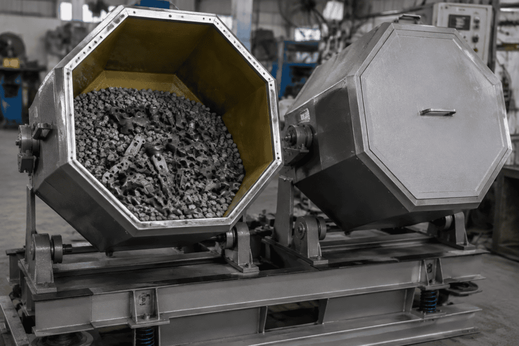
A flat surface polishing machine is equipment that refines the flat faces of metal workpieces—sandblasting-rough plates, saw-cut blanks, machined seal faces, decorative stainless sheet—down to a defined surface condition: a target roughness (Ra), a consistent grain direction, or a mirror gloss, and in some configurations a corrected plane. The category covers both part-level machines (single- and double-disc lapping and polishing machines, rotary-table polishers) and plate-level machines (gantry reciprocating polishers, wide-belt lines for stainless sheet).
The distinction matters because “flat surface polishing” sits at the intersection of two jobs that look similar and are engineered completely differently. One job is *appearance*: brushed #4 finish on stainless panels, uniform satin on appliance fronts. The other is *geometry*: a valve plate or sealing land that must be flat within a few microns so it seals. Some machines do the first, a smaller family does the second, and buying the wrong one is an expensive mistake. This guide separates the equipment types, the process physics, and the selection logic—including the honest boundary between what dedicated flat-polishing equipment achieves and what a robot can, covered in our robotic polishing machine guide.

The Four Main Types of Flat Surface Polishing Equipment
Single- and Double-Disc Lapping and Polishing Machines
The oldest and most precise format. One or two cast-iron or composite discs rotate horizontally, and parts ride inside carriers—often called planetary gears or lantern gears—that are themselves driven to rotate and orbit between the discs. Because the part never sits still relative to the abrasive path, wear on the plate stays even and the finish develops uniformly across the face.
In lapping configuration, the machine runs with loose abrasive in a carrier fluid (diamond, boron carbide, or aluminum oxide slurry); in polishing configuration, it runs with a fixed abrasive pad or a soft cloth with fine slurry to take the surface from a ground matte to a reflective finish. Double-disc machines hold the part between an upper and lower plate and finish both faces in one setup, which is also how they correct flatness: the plates themselves are flat to within microns, and the process transfers that geometry into the part. Single-disc machines finish one face at a time and dominate lower-volume or single-sided work such as sealing faces on housings.
Discs run from 300 mm benchtop units to 1,500 mm production machines; parts from a few millimeters (fuel-injection valve plates) to several hundred millimeters (die plates).
Gantry (Portal) Reciprocating Polishers
A large fixed table—often magnetic or vacuum—holds the workpiece, and a bridge carrying one or more polishing or brushing spindles traverses back and forth across the face in an overlapping raster pattern. Contact pressure is set by pneumatic or servo-controlled Z-axis force. These machines handle parts that are too big or too heavy for a disc: machine bases, large molds, compressor and pump housings, brushed stainless panels up to several meters long.
Multi-head versions stage coarse and fine operations across the bridge, or split the table into zones so one operator loads while the machine polishes the other half.
Rotary-Table (Indexing) Polishers
A round indexing table with four to eight stations rotates parts through a fixed sequence: rough sanding, fine sanding, brushing, buffing, and often a wash or blow-off station. Each station runs a dedicated tool, so the grit progression never has to be swapped mid-cycle. Cycle time equals the longest single station, which makes these machines the natural choice for volume production of round or polygonal parts with a dominant flat face—cookware bottoms, saw blades, pump covers, flanges.
Wide-Belt Through-Feed Machines
Plates or coils pass horizontally through a sequence of contact rolls and brushes—abrasive belt stations for stock removal and grinding, then nonwoven or buffing rolls for brushed and mirror finishes on stainless, aluminum, and brass sheet. Working widths of 650 to 1,350 mm are common, with wet and dry variants. This is the equipment behind decorative stainless sheet (architectural panels, elevator cabs, appliance skins), where the entire product is a flat polished surface. Note the family boundary: a through-feed machine built to grind and brush sheet has close cousins built to deburr laser-cut blanks—see the comparison below and our sheet metal deburring machine guide for that branch of the family.
How the Material Actually Comes Off: Three Abrasive Mechanisms
Every machine above removes metal through one of three mechanisms, and which one a machine uses tells you what it can and cannot do.
Fixed abrasive (belts, discs, films). Grit bonded to a substrate shears microscopic chips off the surface. Aggressive per pass and easy to control by grit selection—typical sequences run 80–120 grit for stock removal, 180–240 for sanding, 320–400 for pre-polish, then nonwoven or buff. It produces directional scratches, which is exactly what a brushed finish is; the machine’s job is making them uniform in depth and direction.
Loose abrasive in a fluid (lapping). Free particles roll and slide between the plate and the work under load, fracturing the surface peaks rather than shearing chips. Removal rates are low—microns per minute, not tenths of a millimeter—but the process is indifferent to the part’s shape and reaches everything the plate touches. This is the mechanism that produces flatness, because the abrasive film self-corrects: high spots on the part see more pressure and wear faster until the face conforms to the plate.
Bound-plus-compound buffing. A rotating wheel of cloth or nonwoven material carrying a polishing compound (tripoli, alumina-based whites, chrome greens) flows and smears the surface at the microscopic level, folding scratches into one another until the surface reflects. Stock removal is nearly zero; the finish comes from wiping, not cutting. Mirror results on flat work are typically achieved buff-and-inspect, with Ra commonly reaching 0.02–0.05 µm on stainless.
| Mechanism | Typical Ra achieved | Directionality | Changes flatness? |
|---|---|---|---|
| Fixed abrasive (belt/disc) | 0.2–0.8 µm depending on grit | Strong (this defines “brushed”) | Slightly, and not in a controlled way |
| Loose abrasive (lapping) | 0.05–0.15 µm | None (isotropic matte) | Yes—primary purpose |
| Buffing with compound | 0.02–0.05 µm on stainless | Weak to none | No |
One practical rule follows from this table: if your drawing calls out flatness and Ra, you almost always need the lapping mechanism in the chain somewhere. Belts alone can hit an Ra number while leaving the part’s geometric errors untouched.
Surface Targets: Ra, Grain Direction, and Gloss
Specifying a flat polished surface means specifying three independent things.
Roughness (Ra or Rz). From a saw-cut or rough-milled finish around Ra 1.6–3.2 µm, each grit step drops Ra by roughly half; production polishing floors in the 0.1–0.4 µm range are normal for functional faces, while decorative and sealing work pushes below 0.1 µm. Verify the number the same way the customer will—a profilometer reading is a contract; “looks shiny” is not.
Grain direction. On brushed finishes, the scratch pattern must run one direction across the whole face, which constrains machine choice: reciprocating and through-feed machines naturally produce linear grain, while rotary-table polishers can leave circular swirl if the path isn’t planned. Multi-part batches are the hard case—grain must survive part-to-part indexing, and mismatched grain is the most common cosmetic rejection on stainless assemblies.
Gloss. Mirror finishes are graded by reflectivity or against industry sample standards for stainless. Gloss is fragile: a handling slip or a worn final buff puts visible haze into a mirror panel, so high-gloss lines invest as much in handling and inspection as in the polishing itself.
Typical Workpieces and Where They Come From
- Valve plates and pump seal faces (compressor valve plates, hydraulic manifolds, fuel-system components): flatness within 2–5 µm and Ra below 0.1 µm so the seal closes. Double-disc lapping territory. Where the surrounding geometry—ports, bores, cross-drilled edges—creates burrs near the sealing land, the burr side of the process is covered in what is robotic deburring.
- Flange and fitting sealing faces: raised faces on flanges are refinished to a mandated finish band (commonly Ra 3.2 µm and below, often with a spiral or phonographic serration). Dedicated flange-facing and lapping equipment serves maintenance shops; production flanges go through double-disc lines.
- Die and mold plates: template and bolster faces that must sit flat under clamping. Lapping or reciprocating finishing depending on size.
- Precision pads, gauge blocks, and machine-tool parallels: the classic lapping products, with flatness measured in fractions of a micron.
- Stainless steel decorative sheet and panels: architectural, elevator, appliance, and food-equipment surfaces in #4 satin, hairline, or #8 mirror—wide-belt territory by definition. A related production case: valve bodies and similar cast parts whose gasket faces need flatness after machining—see our valve body robotic grinding solution for the casting-side process that precedes any sealing-face finishing.
- Large fabrications: machine bases, frames, and weldments whose reference faces are milled and then finished in place—increasingly a robot job rather than a dedicated machine (below).
Selection Factors That Actually Narrow the Choice
1. What does the drawing demand: flatness, Ra, or appearance? Flatness callouts of a few microns send you to double-disc lapping and nothing else. Ra-only callouts on flat faces can be met by belt or pad machines at a fraction of the cost. Pure appearance (grain, gloss) frees you to choose by part size and volume.
2. Part size and weight. Discs limit you to parts that fit within the carrier orbit and, on double-disc machines, parts the plates can float. Parts over roughly 600 mm, or anything measured in hundreds of kilograms, move you to gantry reciprocating or robotic solutions.
3. Volume and takt. Through-feed and rotary-table machines pay off above a few thousand parts per month or wherever a takt under a minute matters. Job shops running hundreds of different parts per month lean toward flexible gantry or robotic cells, accepting longer per-part cycles.
4. Wet or dry. Wet processing—with coolant or water-borne abrasive—controls heat (critical on thin plates that warp), keeps abrasives cutting instead of loading, and handles the slurry from lapping. Dry lines are simpler, cheaper to maintain, and standard for brushed decorative work, but demand dust collection and careful heat management on stainless.
5. Material mix. Aluminum loads abrasives and demands lower pressures; hardened tool steel needs harder wheels and more time; copper alloys smear. A line tooled for stainless sheet will underperform on mixed job-shop work, and vice versa.
6. Loading and unloading. At production volumes, handling dominates labor cost. Vacuum and magnetic fixturing, part robots, and magazine loaders frequently cost more than the polishing station itself—plan them from day one rather than retrofitting.
Flat Surface Polishing vs. Sheet Metal Deburring Machines
The two categories are frequently confused because both are flat-deck machines that pass metal under abrasives, and some models genuinely do both. The engineering intent differs:
| Flat surface polishing machine | Wide-sheet deburring machine | |
|---|---|---|
| Primary target | The face of the part: Ra, grain, gloss, flatness | The edges: burrs, oxide, edge radius |
| Typical part state | Blank or machined face needing refinement | Laser/plasma/punch-cut blanks fresh from cutting |
| Key tooling | Lapping plates, polishing pads, buff rolls | Abrasive belts, rotary brushes, disc brushes |
| Success metric | Profilometer reading, visual standard | Burr-free edge, radius 0.3–2 mm, clean cut face |
Modern wide-belt machines blur the line deliberately—multi-station units pair a coarse grinding belt (deburring and stock removal) with rotary brushes (edge rounding) and a fleece or nonwoven belt (surface finishing) in one pass, which is how a single machine can take a cut blank to a deburred, edged-rounded, satin-finished state. If your parts are cut blanks and the requirement is “flat, deburred, presentable,” that combined machine is usually the right buy, and the selection logic is covered in detail in our sheet metal deburring machine guide. If the requirement is a specified Ra or flatness on the face itself, you need the polishing-side equipment in this guide.
When Robotic Flat Polishing Makes Sense
A dedicated flat-polishing machine assumes the part comes to the machine and presents a flat face in a repeatable fixture. When that assumption breaks down, a robot with force control starts competing:
- Very large workpieces. Machine bases, press beds, and large weldments that cannot be lifted onto a table get finished where they sit—or on their own conveyor—by a robot carrying a sanding or polishing spindle with active force control. See the machine base robotic grinding solution for a production example of large-face finishing on parts no disc machine could accept.
- High-mix, low-volume production. When the batch is 20 parts today and a different casting tomorrow, re-fixturing for a dedicated machine costs more than the polishing. A robot cell reprograms in hours and holds process data per part number.
- Faces that are mostly flat but not only flat. A part with a flat face plus surrounding geometry—tops, chamfers, pockets—can be finished in one robotic setup, where a disc machine would need separate operations and transfers.
- Dangerous or dirty work. Dry sanding large plates throws dust and demands sustained force—things robots absorb without complaint or compensation claims.
The robot’s trade-off is speed and ultimate precision: it is slower per part than a through-feed line, and—critically—it does not correct flatness, as the next section is honest about. Selection logic for robot cells, force control types, and cost structures is laid out in the robotic polishing machine guide.
The Flatness Boundary: What Double-Disc Lapping Does That Robots Cannot
This is the point where overselling happens, so it deserves plain language.
A robot polishing a flat face can deliver an excellent and very repeatable *surface*. Six-axis repeatability is in the sub-0.1 mm class and closed-loop force control holds contact pressure within a band of a few newtons—tight enough to hit a specified Ra on a compliant tool, part after part. What the robot cannot do is *measure and remove the geometric error of the face*. If the part came off the mill with a 20-micron bow, the robot will polish that bowed surface to a beautiful, uniform Ra, and the part will still be bowed 20 microns—arguably worse, because the defect is now harder to see.
Double-disc lapping does the opposite by construction. The process removes material in proportion to local pressure, and local pressure is highest where the part stands proud of the plates, so the high material disappears first. Production double-disc machines routinely hold flatness in the 1–3 µm range on suited part geometries, with sub-micron results on gauge-class work. No path-following machine—robot, gantry, belt line—has this self-correcting property, because their material removal follows the tool path, not the error map.
The engineering conclusion, not the sales conclusion:
- Flatness within a few microns + fine Ra → double-disc lapping (possibly preceded by double-disc grinding for stock removal; the grinding side of that chain is covered in our precision grinding overview).
- Flatness not called out, Ra or appearance required → belt, pad, or robotic polishing on cost and volume logic.
- Large part, moderate flatness → mill it flat first, then finish with a robot or gantry; do not expect the finishing step to rescue geometry.
Frequently Asked Questions
What is the difference between flat polishing and flat lapping?
Lapping uses loose abrasive rolling between a flat plate and the workpiece; polishing (in the strict sense) uses a fixed pad or cloth with fine abrasive or compound. In practice the terms blur: many “flat polishing machines” are lapping machines running a polishing plate, and the meaningful question is whether the process uses loose abrasive (which corrects flatness) or fixed abrasive and buffing (which refine appearance only).
What Ra can a flat surface polishing machine achieve?
With a normal belt-and-buff chain, flat parts finish in the Ra 0.1–0.4 µm range reliably. Lapping followed by polishing takes functional faces to 0.05–0.1 µm, and buffed decorative mirror work on stainless reaches roughly 0.02–0.05 µm. Numbers below that range belong to ultra-precision polishing of optics and wafers—different equipment, different budget.
Can one machine do flatness correction and a mirror finish?
Not in one operation, and usually not in one machine. Flatness comes from loose-abrasive lapping; mirror gloss comes from buffing, and buffing removes almost nothing. Production lines run lapping (geometry) then polishing/buffing (appearance) as separate stations, often on double-disc machines that convert between lap plates and polishing pads.
Flat surface polishing machine or sheet metal deburring machine—which do I need?
If your parts are laser- or punch-cut blanks and the complaint is burrs and sharp edges, you need a deburring machine—many include a finishing module that covers light surface refinement too. If your drawings call out Ra or flatness on faces, you need polishing-side equipment; the multi-station combination machine handles deburring plus finishing, not precision flatness work.
When is a robot better than a dedicated flat polishing machine?
When parts are too large or heavy to fixture on a machine, when the mix changes too fast to justify hard tooling, or when the “flat” face is one feature among several needing finishing in the same setup. Accept the two limits up front: per-part cycle time will be longer than a through-feed line, and the robot will not improve flatness—geometry has to be correct before finishing starts.
The Bottom Line
Flat surface polishing is not one process but a family: lapping for geometry, belts and brushes for grain and finish, buffing for gloss, robots for size and flexibility. Choose by what the drawing actually specifies—flatness, Ra, or appearance—then by part size and volume, and treat wet/dry and automation as the cost levers they are. The most expensive machine in this category is the one bought for the wrong mechanism: a belt line that can never deliver flatness, or a lapping machine idled on cosmetic work it was never needed for. Define the surface in measurable terms first, then let the equipment follow.