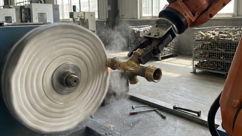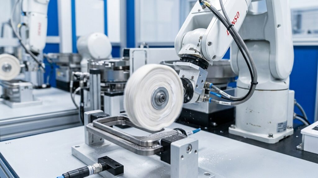
の中で 3C家電 sector, the cosmetic texture of a smartphone is a core element of purchase appeal. As flagship models shift from aluminum to ultra-hard stainless steel and Titanium, the mirror polishing and micro-hole deburring of the mid-frame have become one of the hardest problems for OEMs and EMS providers. This article explores how, in high-volume production, highly agile industrial robots holding workpieces against heavy-duty floor-mounted polishing centers—integrated with advanced 自動化システム—address industry pain points like titanium orange peel and antenna-step defects, delivering jewelry-grade results consistently.
スマートフォンのメタルミッドフレームとは?
スマートフォンのミッドフレーム(またはシャーシ)は、デバイスの骨格である。スクリーン、バックカバー、マザーボードを支えており、極めて重要なことに、ユーザーが物理的に触れ、視覚的に注目する主要な外観部品である。.
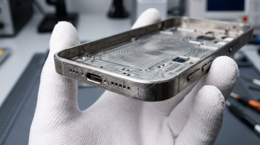

Smartphone Mid-Frame Polishing Scenarios
究極の触感と見た目の高級感を実現するため、(最新のProシリーズのような)トップ・フラッグシップ携帯電話のミッドフレームは通常、チタン合金や高硬度の医療用ステンレス鋼から鍛造され、超精密CNCフライス加工が何十工程も施される。.
Straight off the CNC machine, the frame is covered in microscopic milling tool marks. Furthermore, sharp micro-burrs are left around the tiny volume button holes, USB-C ports, and speaker arrays. If not subjected to thorough surface blending and polishing, this leads directly to poor adhesion and color variance in subsequent PVD coatings, and can even cut the user’s fingers. Proper micro-hole deburring has its own toolbox—see our guide to robotic deburring fundamentals for how dedicated equipment handles these features.
Smartphone Mid-Frame Structural Characteristics
これらのフレームの表面処理は、物理的に非常に困難な問題に直面している:
- 極めて脆弱なマイクロホール:フレームのエッジには、わずか1~2mm幅の穴が開いている。研磨力が強すぎると、瞬時に穴が変形したり、穴の縁がつぶれたりする。.
- 異種材料のシームレス接合:金属フレームにはプラスチック/樹脂製のアンテナバンドが埋め込まれています。研磨時の莫大な摩擦熱により、プラスチックは容易に溶けるか、金属とプラスチックの境界に鋭い「段差」が生じます。.
- チタンの極端な粘着性と感熱性:チタンは熱伝導が悪い。従来の研磨では、表面が激しく熱せられ、目に見える「オレンジピール」と呼ばれる波紋や熱変色が生じます。.
スマートフォンのフレーム研磨の主な特徴
主な特徴:
- 絶対的な光沢/マット性: Whether requiring a mirror reflection or a fine brushed matte, across tens of millions of units, the first and the ten-millionth smartphone frame must look identical.
- ゼロエッジ丸め:研磨は、CNCによって削り出された鋭い直角のエッジを破壊したり、スクリーン組立の厳しい公差に違反してはならない。.
- 極端なサイクルタイムと歩留まり: Smartphones have short lifecycles. Contract manufacturers must compress the frame’s cycle time to the limit while keeping finishing yields at the level consumer-brand audits demand.
電話フレーム研磨の技術パラメーター
| 項目 | パラメータ範囲 | 備考 |
| 微細穴バリ取り | カスタムマイクロSiCナイロンブラシ | 直径を変えずに1mmの穴を掃引 |
| チタン平坦化 | 高密度サイザル麻/コンポジット | 冷却カットワックスでCNCステップを消す |
| ミラー・ディープ・ポリッシュ | ソフトコットン+高光沢ワックス | Produces a deep, clear mirror luster |
| 接触力制御 | 5N~15N(高域アダプティブ) | プラスチックアンテナを保護し、変形を防ぐ |
| サイクルタイム | 60~90年代/ピース | 密閉された単一セル内での超高速出力 |
なぜプレミアムフレームは “ロボット-ワークピース-保持 ”アーキテクチャーを使わなければならないのか?
小さいが非常に複雑な3C構造部品を加工する場合、業界標準は 左側の6軸産業用ロボットがミッドフレーム(ワーク)を確実に把持し、右側の床にしっかりと取り付けられた頑丈なマルチステーション研磨機(ツール)に対して正確に操作する。.
手動または単純専用機の欠点
| ペイン・ポイント | 特定の問題 | インパクト |
| 悲惨なアンテナ・ステップの違い | 手動では力が不均等で、柔らかいプラスチック製のアンテナは瞬時にえぐり取られる。. | 高級ユニットはスクラップされる。. |
| チタンオレンジピール | 砥石の温度はスパイラル状に上昇し、チタンは急速に局所的な熱を持つ。. | 不可逆的なオレンジピールを生じ、PVDコーティングを台無しにする。. |
| 野生の能力と収量変動 | 何百人もの労働者の体力に全面的に頼っている。. | 収量は激しく変動し(80%-90%)、マージンを食い潰している。. |
重量級ロボットセルの圧倒的優位性
| 比較 | 伝統的な研磨 | ロボット把持部+力制御 | 改善 |
| 複素曲率 | 硬く、デッドゾーンが残る | ロボットがベルトに対して部品を反転させ、ひねる | サイドとRコーナーの完璧でデッドゾーンのないトランジション |
| 異種材料 | 原因 | ミリニュートンの力応答はプラスチック上で瞬時に降伏する | チタンとアンテナの間の継ぎ目のない完璧な平坦性 |
| ヒートコントロール | オレンジピールの原因 | 高速ロボット掃除+自動ワックススプレー冷却 | オレンジピールを除去し、ジュエリーレベルのミラーを残す |
| アジャイル・チェンジオーバー | 新しい治具が必要 | OLPワンクリック電話機種変更 | 過酷な6ヶ月の3C反復サイクルに完璧に適応 |
コア・アドバンテージアクティブ・フォース・コントロール.
As the robot grips the phone frame and presses its edge against the fast-spinning floor-mounted buffing wheel on the right, the force sensor detects the resistance shift from “hard titanium” to “soft antenna band” in milliseconds. The robot automatically reduces contact pressure, gliding over the plastic before restoring pressure. This “smart floating contact” keeps a delicate phone frame dimensionally accurate even under the friction of heavy machinery—an approach our robotic polishing machine guide covers in more detail for other part families.
スマートフォンのフレーム研磨工程を自動化するワークフロー
完全に密閉された産業用セルの中で、ロボットは右側の頑丈な床置きポリッシング・センターと協働し、極めてコンパクトな8つのステップを完了する。.
スマートフォン中枠ロボット研磨・バリ取り工程フロー
| ステップ | プロセス名 | 機材レイアウト | 時間 | 精度/目的 |
| 01 | ビジョンガイド付きローディング | 視覚を使ってトレイから部品をつかむロボット | 5s | 素早く正確なグリップで、正しい軌道の原点を確保。 |
| 02 | 微細穴バリ取り | 固定されたマイクロブラシに部品を押し付けるロボット | 15s | USB&ボタンホールからマイクロフラッシュをソフトにスイープ |
| 03 | エッジ粗平坦化 | ロボットが大型のサイザル麻ステーションに移動 | 25s | CNC マークをカットし、金属/プラスチック・アンテナの継ぎ目を水平にする。 |
| 04 | チタン配合 | ロボットがソフトコンポジットホイールに移動 | 20s | キズを磨き、コールドワックスで温度を厳密にコントロール |
| 05 | エッジ・ミラー・ポリッシュ | ロボットが柔らかいコットンホイールに移動 | 25s | 高速バフが、クリアで深みのある鏡面光沢を呼び覚ます |
| 06 | インライン高圧脱脂 | ロボットが部品をスチームノズルに移動 | 10s | 穴の中で固まる前に柔らかいワックスを瞬時に吹き飛ばす |
| 07 | ディープ超音波洗浄 | 工場裏の多槽ライン | 120s | PVDに必要な極めて高い表面清浄度を実現 |
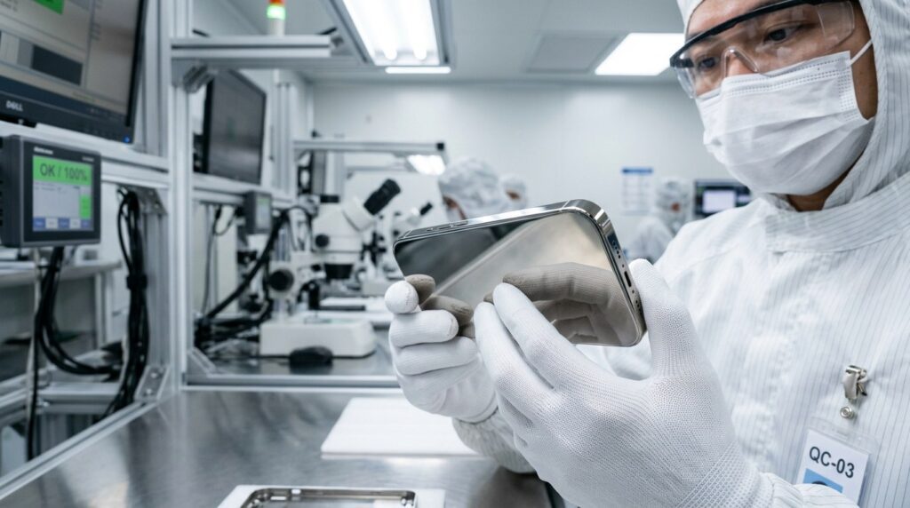
| 08 | 自動光学検査. | AOIビジョン・トンネルカメラの比較 | 15s | 10ミクロン以上のスクラッチ、ピット、オレンジピールは自動除去されます。 |
Process Workflow Notes
Deburring comes before buffing, deliberately. Micro-hole flash is easiest to remove while it is still crisp and before polishing wax has had a chance to pack into the holes. The brushing station (step 02) runs a custom SiC nylon brush sized for the smallest hole diameter in the frame; the robot presents each hole array to the brush at a controlled angle so the bristle tips—not the stem—do the cutting. This keeps hole diameter and edge geometry untouched, which matters because downstream PVD coating thickness is specified with the as-machined dimensions in mind.
Antenna bands are the force-control proving ground. At the sisal flattening station (step 03), the robot sweeps the frame edge across the wheel with the long axis of the antenna strip aligned to the pass direction. When the wrist sensor registers the resistance drop of polymer against metal, contact pressure drops within milliseconds and the wheel bridges the insert instead of digging at its boundary. The measured step between titanium and antenna surfaces is the KPI this station lives and dies by—it determines whether the frame feels seamless to a fingernail and whether PVD color coats the transition evenly.
Dewax timing is a race against congealing. High-gloss wax starts to set within seconds of leaving the buff. The steam station (step 06) therefore sits directly beside the final polish wheel inside the same cell, and the robot moves the frame there immediately after the last pass—before the wax can lock into speaker-hole arrays. A missed dewax window shows up later as wax residue surviving the ultrasonic line and contaminating the PVD chamber.
Inspection closes the loop. The AOI tunnel (step 08) compares each frame against a golden-sample image library; flagged frames route automatically to a rework or reject lane rather than drifting into the coating line. Defect statistics feed back to the force-control setpoints, so a drift toward orange peel at the titanium blending station is corrected at the process level rather than caught part by part.


機械加工の困難と解決策
Difficulty 1: Titanium Orange Peel Under High-Cycle Buffing
問題点: Titanium conducts heat poorly, and the mirror finish demanded of flagship frames requires sustained wheel contact. As surface temperature climbs, the material softens locally and the wheel begins to plow instead of cut, leaving a rippled “orange peel” texture that no amount of re-buffing removes—usually the part is scrapped.
ソリューション: Cut the heat budget at every station. Robot passes are programmed fast and light rather than slow and heavy; atomized wax spray cools the interface continuously; and the process splits stock removal across multiple stations (sisal, composite, cotton) so no single wheel does enough work to overheat the surface. The result is a stable process window where the surface stays hard throughout the sequence.
Difficulty 2: Step Formation at Metal-Antenna Boundaries
問題点: Antenna strips are polymer—orders of magnitude softer than the surrounding titanium or stainless. Any fixed-position polishing pass removes polymer faster than metal, leaving a sunken antenna band that users can feel with a thumbnail and that no downstream process can hide.
ソリューション: Sensored, not scheduled, pressure relief. The wrist-mounted force/torque sensor detects the material transition in real time and relieves contact force the moment the wheel reaches the insert, then restores it on the far side. Because the response is measured rather than programmed, it tolerates strip-position variation from part to part and from supplier lot to supplier lot.
Difficulty 3: Cycle Time vs. Cosmetic Consistency at Scale
問題点: Consumer electronics runs are enormous and unforgiving: the finish standard set by the first article must hold across millions of units, while the per-piece time budget stays in the range of a minute or two.
ソリューション: Architect the cell for parallelism and consistency rather than raw speed. Workpiece-holding robots overlap motion with polishing time, stations run simultaneously, and every frame executes the identical force-controlled program—so the process scales by adding cells that behave the same way, rather than by pushing any single line harder. For related cell layouts and tooling choices, see our overview of deburring machine types.
Application Scenario
Production Background
A representative deployment for this equipment is a smartphone structural-component contract manufacturer (EMS) in South China ramping titanium mid-frames for a flagship program. The scenario below describes the typical production problem and how the cell layout responds.
技術的課題
- The new titanium program replaced a stainless-steel frame process. Legacy polishing lines, tuned for stainless, produced elevated scrap on titanium—driven mainly by sunken antenna bands and orange peel.
- Daily volumes for the program are in the six figures, so the finishing line had to scale in parallel with CNC output rather than become the tail bottleneck.
ソリューション
The deployment is an array of fully enclosed robotic cells. Inside each cell, a 6-axis robot on the left grips the phone frame and processes it against heavy-duty floor-mounted polishing machines on the right, with milli-Newton active force control and wax-spray cooling integrated into every polishing station. The per-piece polishing cycle sits in the one-to-two-minute range, and cells are duplicated to match the program’s daily volume.
What the Layout Changes in Practice
- Yield stabilization: With force control managing the antenna transition and the split-station heat strategy on titanium, the defect modes that dominated manual-line scrap—antenna steps and orange peel—drop to a minor share of overall loss, and polishing yield stabilizes at a high level.
- Scalable capacity: Because every cell runs the identical program, output scales predictably with cell count on a 24/7 schedule, and the finishing line keeps pace with upstream CNC output.
- Reduced dependence on scarce skills: The process no longer leans on a large bench of experienced hand polishers, which removes both a staffing constraint and a source of unit-to-unit variation.
よくあるご質問
Q1: 重研磨機にフレームを押し付けると、正確なシャープエッジが丸くなりますか?
A: Not when the cell is set up correctly. This is why Active Force Control and Offline Programming (OLP) are used together. The robot holds the frame at a precise tilt angle, letting the edge meet the cloth wheel at a controlled contact geometry while the force sensor maintains a constant, very light pressure. This “zero edge rounding” technique preserves the sharp lines cut by the CNC.
Q2: スピーカーの小さな穴に研磨ワックスが詰まらないようにするにはどうしたらよいですか?
A: Inside the cell, immediately after the final cloth buffing step (and before the wax can cool and congeal), the robot moves the frame to an adjacent high-pressure, high-temp steam nozzle station. This blasts the residual wax out of the micro-holes while it is still soft, so the holes arrive at the ultrasonic line fully open.
Q3:ロボットと床置き重機で構成されるこのシステムでは、機種変更は難しいのでしょうか?
A: Changeover is fast by design. Based on OLP software, engineers simply import the 3D CAD model of the new phone casing. The software automatically plans the robot’s gripping posture and its trajectory against the polishing machine on the right. Pushing the new program to the cell typically compresses changeover and debugging to a matter of minutes.
結論
In the competitive manufacturing ecosystem of 3C consumer electronics, the surface treatment of titanium and stainless steel frames is a decisive factor in an EMS provider’s ability to hold a flagship program. Adopting an 頑丈な6軸ロボットと巨大な床置きポリッシングセンターでワークを保持する自動化構造, augmented by micron-level active force control, addresses the step defects, orange peel, and yield swings that come with manual polishing. It sustains jewelry-grade mirror finishes across millions of frames with stable, fast cycle times.
If you are bogged down by low yields in 3C frame polishing, facing brand rejections due to antenna step differences, or struggling with severe labor shortages, contact our automation expert team to arrange a dedicated high-volume polishing technical assessment.