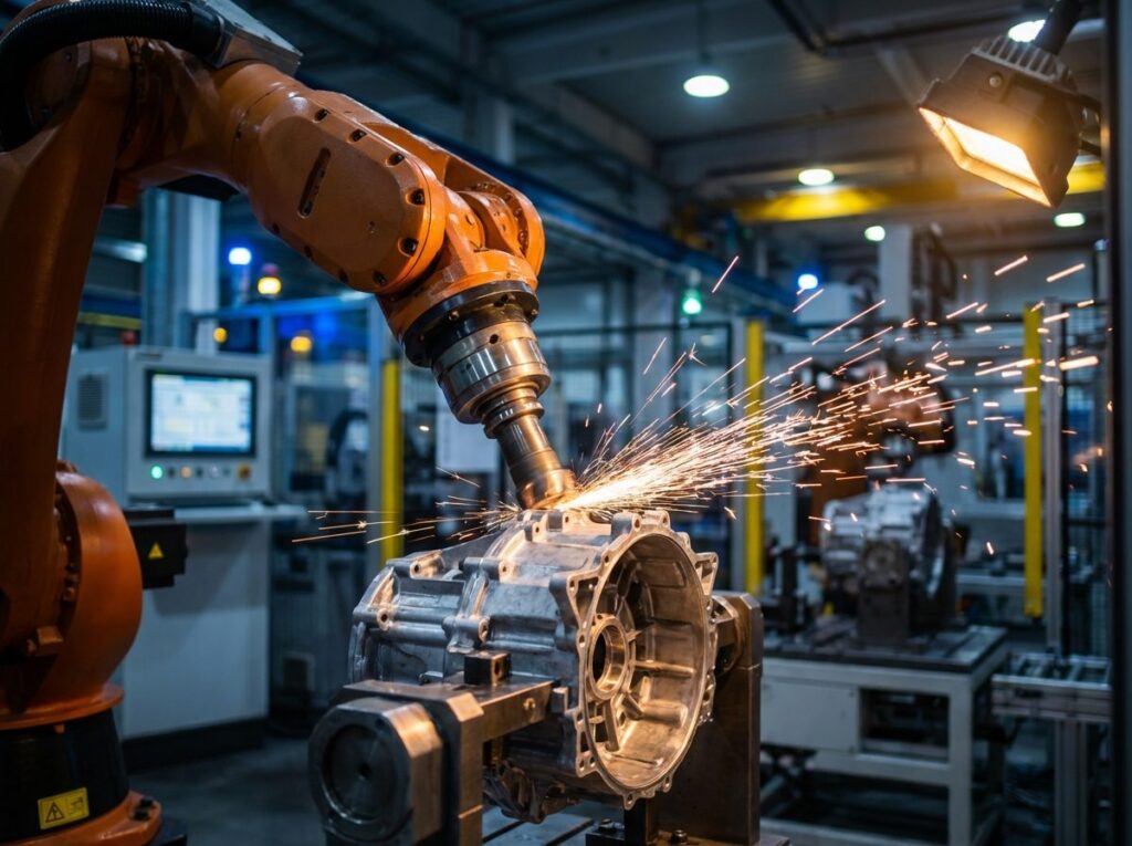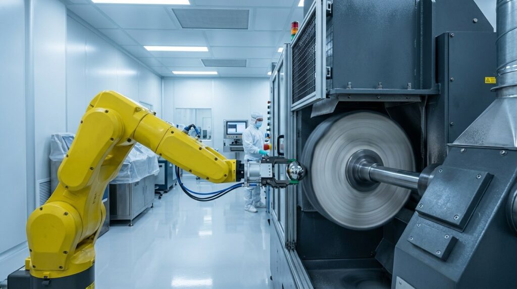
In medical device manufacturing, the surface treatment of artificial joint implants (such as the femoral head of a hip joint or the condyle of a knee joint) directly correlates to the clinical lifespan of the implant, wear debris rates, and ultimately, the patient’s quality of life. These high-value components are typically manufactured from extremely hard Cobalt-Chromium-Molybdenum (CoCrMo) alloys or Titanium alloys. This article examines how medical-industry finishing equipment applies the robot-holding-workpiece architecture—heavy-duty industrial robots maneuvering workpieces against floor-mounted polishing stations—to achieve mirror finishes in the Ra 0.01-0.05 μm range while holding spherical and bionic-contour tolerances, and how these processes are designed to support customer validation in regulated production environments.
人工関節インプラントとは?
Artificial joint implants are precision metal components designed to replace severely damaged or diseased joints (such as hips and knees) within the human body. Taking a total hip replacement as an example, the metal Femoral Head is typically only the size of a golf ball, yet it must articulate against an ultra-high-molecular-weight polyethylene (UHMWPE) or ceramic liner for millions of load cycles over decades of service.
Material Split: CoCrMo vs. Titanium
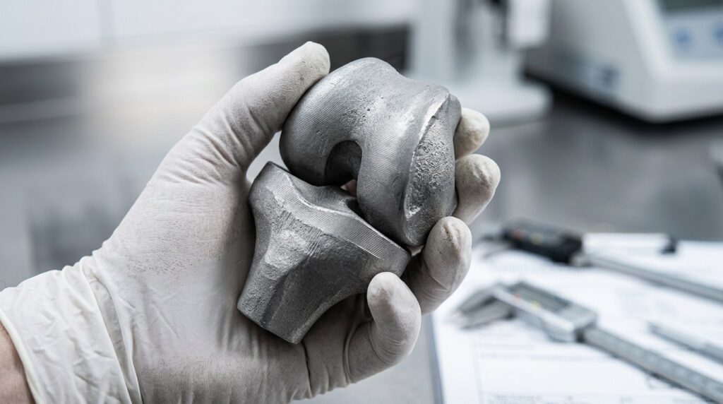
Joint implants are not machined from a single material—the alloy is matched to the function of each surface:
- CoCrMo (Cobalt-Chromium-Molybdenum): The default choice for articulating surfaces—femoral heads, knee femoral condyles, and bearing inserts. It combines high hardness, excellent wear resistance against UHMWPE, and the ability to take a mirror finish. Both investment-cast (ASTM F75-type) and wrought (F1537-type) grades are common.
- Ti-6Al-4V Titanium Alloy: Used mainly for stems and bone-contacting components, where its lower elastic modulus and biocompatibility support osseointegration. These surfaces are deliberately not mirror-polished—they are left rough, textured, or porous-coated so bone can anchor to them.
This split defines the polishing task: remove machining marks and bring only the articulating surfaces to a super-finish, while protecting adjacent bone-integration surfaces from any accidental glossing or contamination. A related process for trauma and spinal implants is covered in our article on orthopedic implant robotic polishing.
Applications: Where Joint Polishing Matters
| Implant Component | Typical Material | Surface Requirement |
| Hip femoral head | CoCrMo (or ceramic, polished separately) | Full sphere, Ra typically 0.01-0.05 μm, sphericity in the micron class |
| Knee femoral condyle | CoCrMo | Multi-curvature mirror polish on the bearing surfaces only |
| Acetabular shell / bearing insert | CoCrMo / Ti alloy | Polished bearing face, textured bone-facing side left intact |
| Shoulder humeral head | CoCrMo | Spherical or slightly aspherical mirror finish |
| Femoral stem (taper + body) | Ti-6Al-4V | Taper cleaned and blended; body left rough for osseointegration |
Across all of these components, the consequences of a poor surface are the same: higher friction, accelerated generation of microscopic wear debris, and reduced implant service life. The polishing line is therefore a quality-critical step, not a cosmetic one.
Pain Point: Why Manual Polishing Falls Short
Manual finishing of joint components has three structural weaknesses that process engineering cannot fully compensate for:
- Spheres polished into “ellipses”: A human operator cannot hold a perfectly constant normal force and contact angle while sweeping a femoral head across a spinning buff. Uneven dwell time degrades sphericity, and an out-of-round head scrapping is a direct, measurable loss on a high-value CoCrMo part.
- Thermal and metallurgical risk: CoCrMo is hard and heat-resistant, but excessive dwell still overheats local contact zones; on titanium components, poor heat dissipation makes the risk more acute. Overheating alters surface appearance and can affect the thin surface layer that later processes rely on.
- No usable process data: Manual polishers work by feel. There is no force curve, RPM log, or position record to review when a quality question arises—only the finished part itself.
None of this reflects on the skill of manual polishers—veteran finishers achieve remarkable results on individual pieces. The problem is repeatability: an implant line must deliver the same surface on part number 80,000 as on part number 8, with documented evidence behind every batch.
Key Characteristics of Joint Implant Polishing
- Ultra-low surface roughness: Articulating surfaces typically specify Ra 0.01-0.05 μm depending on the bearing couple and the drawing. Every microscopic scratch left in the surface is a potential wear-debris source once the joint is in service.
- Geometric fidelity (sphericity and contour): Material removal must be small and uniform. Polishing must refine the surface, not re-shape it—the geometry delivered by CNC grinding must survive the polishing line within tolerance.
- Selective surface treatment: Bearing surfaces get mirror-finished; bone-contacting surfaces must stay matte, rough, and untouched. The process needs precise zone control, not blanket coverage.
- Process documentation: Force, speed, and position data for each workpiece support the manufacturer’s quality system and process validation records.
Technical Parameters for Joint Polishing
| 項目 | パラメータ範囲 | 備考 |
| Rough prep grinding | Fine flexible belt / nylon flap wheel | Flattens CNC tool marks, establishes a uniform scratch pattern |
| Sisal pre-polishing | High-density sisal wheel + cutting compound | Refines the scratch pattern into a uniform satin base |
| Free abrasive / lapping (sphere work) | Fine alumina or diamond slurry on lapping plate | Used where the drawing demands the finest sphericity on spherical heads |
| Final mirror buffing | Soft cotton / muslin wheel + fine polishing compound | Brings bearing surfaces to the target Ra range |
| Final surface roughness | Ra 0.01 – 0.05 μm | Per component drawing and bearing couple |
| Contact force control | ±0.5 – 1 N, high-frequency closed loop | Protects sphericity and prevents edge roll-over |
| Pre-passivation cleaning | Degrease + ultrasonic wash + DI rinse | Leaves a clean, residue-free surface ahead of the chemical passivation step |
Why the “Robot-Holding-Workpiece” Architecture?
For small, high-value components like joint implants, the proven cell layout is: a 6-axis industrial robot on the left grips the workpiece and maneuvers it against heavy-duty, multi-station polishing machines mounted to the floor on the right. This is the same architecture used across our robotic polishing machine guide, and it suits implant work for three reasons:
- Milli-Newton force discipline: A high-frequency force/torque sensor on the robot wrist keeps contact force constant as the wheel wears. When the cloth wheel loses diameter, the robot extends its feed within milliseconds—polishing energy stays uniform across the batch, which is exactly what sphericity requires.
- Full articulation around the geometry: Holding the small workpiece lets the robot orient it at any angle against the wheel—sweeping a femoral head across the buff in overlapping great-circle passes, or following a condyle’s curvature changes without tool-change dead zones.
- Multi-station sequence in one cell: Belt, sisal, lapping, and cotton-wheel stations sit side by side. The robot moves the part from station to station without re-fixturing, so datum consistency is preserved through the whole finishing sequence.
Path Planning for Bionic Curves
Knee condyles are asymmetric multi-curvature free-form surfaces—unlike a hip head, there is no single axis to spin around. Offline Programming (OLP) software imports the component’s 3D CAD model, derives the surface normals, and generates a polishing trajectory that keeps wheel contact tangential across every curvature transition. Combined with active force control, the robot follows undulating saddle-shaped surfaces with uniform pressure rather than tracing a taught path that goes stale the moment the wheel wears.
Automated Joint Polishing Process Workflow
| ステップ | プロセス名 | 設備・消耗品 | 目的と精度 |
| 01 | Soft-grip loading | Robot + custom soft-jaw gripper | Scratch-free clamping, repeatable datum |
| 02 | Tool-mark blending | Fine micro-belt / nylon wheel | Flattens CNC marks under constant light force |
| 03 | Sisal pre-polish | Floor-mounted sisal wheel + cut compound | Uniform satin base, temperature-managed with sprayed coolant |
| 04 | Spherical lapping (where specified) | Lapping station + fine slurry | Free-abrasive refinement of spherical heads toward the roundness target |
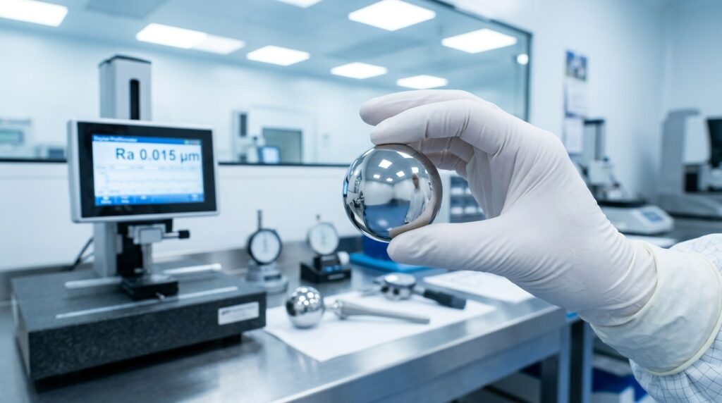
| 05 | Final mirror buffing | Pure cotton wheel + fine compound | Brings bearing surface to Ra 0.01-0.05 μm |
| 06 | High-pressure dewax | Steam / hot pure-water spray | Strips polishing compound before it congeals in recesses |
| 07 | Ultrasonic wash + DI rinse | Multi-tank ultrasonic line | Residue-free surface ahead of passivation |
| 08 | Optical inspection | White-light interferometer / 3D scan | Surface roughness and geometry records for each lot |
Two Workflow Details Worth Noting
Free abrasive lapping is geometry insurance. Buffing a sphere against a cloth wheel refines roughness, but roundness is bounded by how accurately the robot sweeps the surface. Where drawings demand the tightest sphericity, a lapping step with free abrasive (fine alumina or diamond slurry) between pre-polish and final buff averages out local errors—every point on the sphere passes over the same lap surface, so high spots see more action than low spots, and the form converges toward round.
Passivation is downstream, and polishing must respect it. Chemical passivation (typically nitric-acid-based, per the governing material standard) removes free iron from the surface and builds the chromium-oxide layer that underpins corrosion resistance. Polishing does not perform passivation—its job is to hand over a clean, uniform, residue-free surface so the passivation bath can work evenly. That is why the workflow ends with degreasing, ultrasonic cleaning, and a DI-water rinse rather than stopping at the buffing wheel.
機械加工の困難と解決策
Difficulty 1: Sphericity Drift Across the Batch
問題点: A cotton wheel wears continuously. With position-only automation, each successive part meets a slightly smaller wheel at slightly different contact geometry, and sphericity drifts slowly across the batch—an effect that individual parts don’t show but a roundness trend chart does.
ソリューション: Closed-loop force control with wheel-wear compensation. The wrist sensor holds normal force at setpoint; the controller continuously adjusts the feed radius as the wheel shrinks, and periodic in-process touch-off recalibrates the wheel datum. Roundness is verified on a roundness tester per the sampling plan, and the data feeds back into force and dwell parameters.
Difficulty 2: Protecting Non-Bearing Surfaces
問題点: Implant stems and bone-facing surfaces must retain their blasted or porous texture. Any accidental buff contact glosses the surface, interfering with osseointegration and scrapping the part at final inspection.
ソリューション: Zone-masked trajectories and guarded fixturing. OLP paths are generated strictly from the CAD bearing-surface definition, with keep-out volumes around every bone-contact zone; soft fixtures cover clamping contact areas. The robot physically never presents a protected zone to the wheel.
Difficulty 3: Dust, Cleanliness, and Facility Integration
問題点: CoCrMo and titanium polishing generates fine metallic dust, and implant production facilities control particulate and cross-contamination tightly—often with cleaning and packaging operations in classified areas.
ソリューション: Enclosed cells with full extraction, specified to support the customer’s facility concept. Cells can be built with stainless-steel interiors, filtered extraction, and micro-negative pressure so they can sit at the boundary of controlled areas; in a typical layout, grinding and polishing stay in the general production zone, and parts enter the controlled environment only after degreasing, ultrasonic cleaning, and drying. Dust extraction for titanium operations uses wet or similarly rated systems appropriate to the material’s fire behavior.
Application Scenario
Production Background
A representative deployment for this equipment is an implant manufacturer scaling up production of CoCrMo knee femoral components. Parts arrive from CNC with machining marks on the condyle bearing surfaces; the drawing requires a mirror finish in the low Ra range with contour deviations held within a few microns, while the stem interface and bone-facing zones must remain untouched.
Cell Configuration
| 項目 | 構成 |
| ワークピース | CoCrMo knee femoral component / hip femoral head |
| Architecture | Heavy-duty 6-axis robot (workpiece) vs. floor-mounted multi-station polishing center (tool) |
| Stations | Micro-belt blend → sisal pre-polish → lapping (as specified) → cotton mirror buff |
| Core control | High-frequency active force control ±0.5-1 N + OLP trajectories from CAD |
| Auxiliary | Steam dewax, multi-tank ultrasonic wash, DI rinse, drying |
| 検査 | Roughness (white-light interferometer) and roundness/contour records per sampling plan |
What the Layout Changes in Practice
- Roundness stability: With force held constant and wheel wear compensated, sphericity holds within the drawing band across the batch instead of drifting with operator fatigue—and distortion-related scrap falls accordingly, in many cases from a stubborn headache to an occasional event.
- Documented process: Every part carries a force/speed/position record. When a quality question arises, the review starts from data instead of recollection, which shortens investigations and supports the manufacturer’s quality-system documentation.
- Throughput without headcount: One robot tends the full station sequence continuously, so output scales with cell hours rather than with the availability of skilled polishers—a real constraint when experienced finishers are scarce.
よくあるご質問
Q1: Do titanium and CoCrMo components need different polishing processes?
A: Yes. CoCrMo bearing surfaces go through the full sequence—blending, pre-polish, and mirror buffing—to reach the drawing’s roughness target. Titanium components such as stems usually need only gentle blending and cleaning of functional surfaces (tapers, for example), because their bone-contacting surfaces must stay rough for osseointegration. Titanium also conducts heat poorly, so contact force and dwell limits are set more conservatively. The cell runs both, but with separate programs and consumable schedules.
Q2: How does the system hold sphericity on a femoral head?
A: Three mechanisms work together. First, the robot sweeps the head across the wheel in overlapping great-circle passes generated from CAD, so no zone is starved of or overexposed to the wheel. Second, active force control keeps normal pressure constant as the wheel wears, which is what prevents the slow roundness drift that manual and position-only setups suffer. Third, where the drawing demands it, a free-abrasive lapping step physically converges the form toward round. Roundness is then verified on a roundness tester per the sampling plan.
Q3: Can the cell operate inside a cleanroom?
A: Polishing as a process generates dust, so most facilities place grinding and polishing in the general production zone and reserve classified areas for cleaning, passivation handling, and packaging. The equipment is designed to support that concept: stainless-steel interiors, filtered extraction, and micro-negative-pressure enclosures let the cell sit cleanly at the boundary of controlled areas, with parts entering the controlled environment only after degreasing, ultrasonic cleaning, and drying.
Q4: How fast is changeover between implant sizes?
A: New sizes are a programming task, not a rebuild. The 3D CAD model goes into the OLP software, which generates the bearing-surface trajectories and keep-out zones; on the floor, changeover is a program call plus a quick-change fixture swap. For a family of femoral heads differing mainly in diameter, changeover is a matter of minutes; a new condyle geometry with different curvature zones takes longer for path development and first-article verification.
結論
Mirror finishing of artificial joint implants is one of the most demanding surface-treatment tasks in medical device manufacturing: Ra targets in the 0.01-0.05 μm class, sphericity and contour tolerances in the micron range, and strict zone control between bearing and bone-integration surfaces. The automated architecture—a heavy-duty 6-axis robot holding the implant against a floor-mounted multi-station polishing center, driven by active force control and CAD-based path planning—directly addresses the roundness drift, heat management, and documentation gaps of manual polishing.
If your line is fighting sphericity drift on CoCrMo heads, struggling to staff skilled polishers, or simply needs a documented, repeatable finishing process, contact our team for a project assessment and proof-of-concept trial with your component geometry.