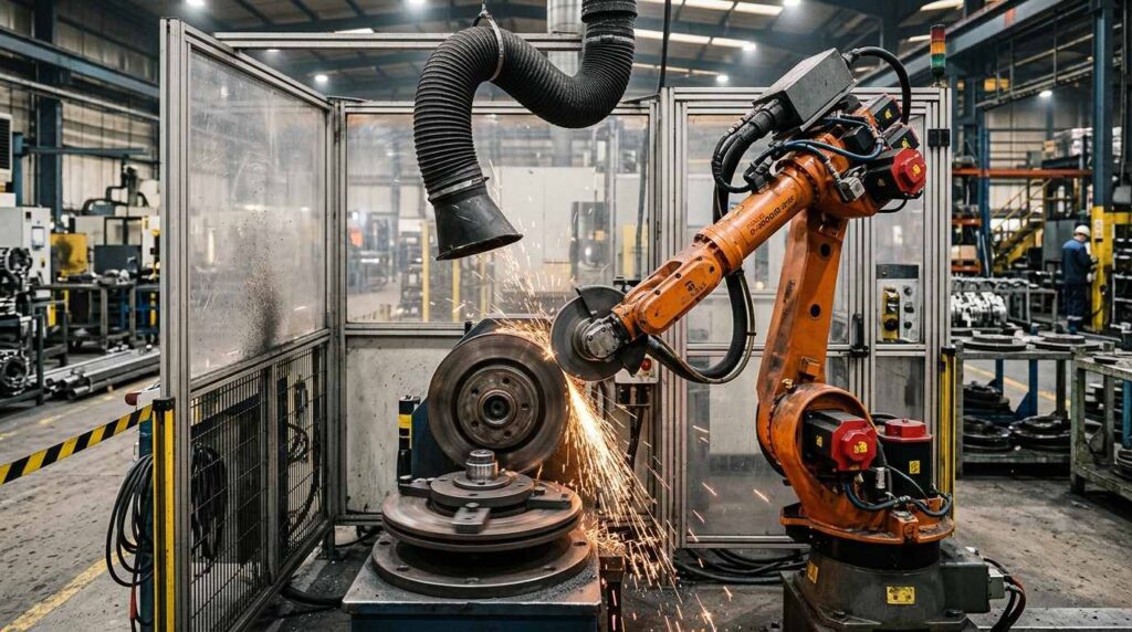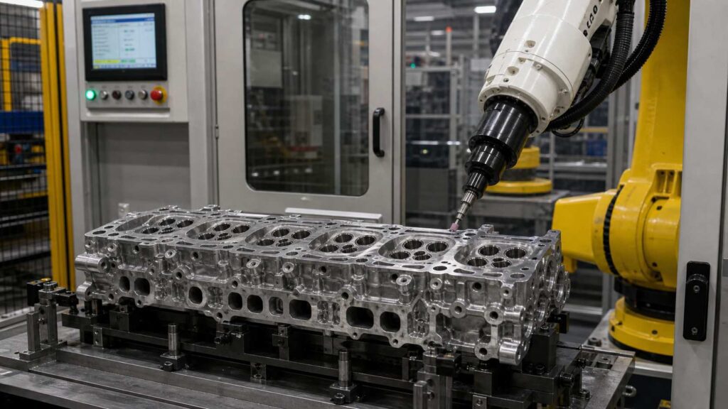
アルミニウム合金製のエンジンシリンダーヘッドは、燃焼室を形成し、バルブトレインの構成部品を支え、吸気・排気・冷却・潤滑通路を接続するために使用される、複雑な自動車用エンジン鋳造部品である。 一般的なシリンダーヘッドの構造に基づくと、このワークピースには燃焼室の縁部、吸気・排気ポート、ウォータージャケットの開口部、オイル通路、スパークプラグまたはインジェクターの穴、ボルト穴、機械加工面、不規則な鋳造輪郭などが含まれており、単純なアルミニウム部品に比べて、鋳造後のバリ取りや局所的な研削がより困難となります。.
このロボットによるバリ取り・研削ソリューションは、エンジンモデルに応じて長さが通常350~650 mm程度のアルミニウム合金製エンジンシリンダーヘッド向けに設計されています。 このソリューションは、ポート開口部、燃焼室境界、水・オイル通路の縁、ボルト穴、外形輪郭、およびキャビティの局所的な移行部から、バリ、フラッシュ、鋭いエッジ、通路縁の残留物、局所的なゲート跡を除去すると同時に、仕上げの均一性を向上させ、重要な機能面を保護します。.
アルミニウム合金製エンジンシリンダーヘッドとは?
アルミニウム合金製のエンジンシリンダーヘッドは、シリンダーブロックの上部に取り付けられる、エンジンの中核をなす鋳造部品です。これには、燃焼室の構成要素、吸気・排気の流路、バルブ関連部、スパークプラグやインジェクターの取り付け位置、冷却水通路、オイル通路、および複数の取り付けインターフェースが含まれていたり、これらを支えたりしています。.
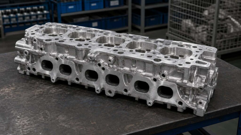
代表的なサンプル構造を見ると、エンジンのシリンダーヘッドはシリンダーヘッドカバーよりもはるかに複雑です。そこには、深い流路、機能的な穴群、燃焼室側の境界、機械加工された取付面、シール面、ねじ穴や精密穴、そして緻密な内部の接合部が存在します。 鋳造、トリミング、粗加工の後、ポート開口部、ウォータージャケットの穴、オイル通路、ボルト穴、燃焼室の縁、および局所的な鋳造部の接合部周辺に、バリ、フラッシュ、鋭いエッジが残っている場合があります。この種のワークピースにおいて、仕上げ加工の主な要件は、装飾的な研磨ではなく、ロボットによるバリ取り、制御された局所研削、および通路エッジのクリーンアップです。.
| 項目 | 詳細 |
|---|---|
| ワークピース名 | アルミニウム合金製エンジンシリンダーヘッド |
| 中国名 | アルミニウム合金製エンジンシリンダーヘッド |
| 典型的なサイズ | モデルによって異なりますが、約350~650 × 180~350 × 100~250 mm |
| 素材 | アルミニウム合金鋳造 |
| 主なプロセス | ロボットによるバリ取り・研削 |
| アシストプロセス | ポートエッジのバリ取り、穴縁の処理、局所的な表面の清掃、エッジの丸み付け |
| 主要な処理分野 | 吸気ポート、排気ポート、燃焼室の縁、水ジャケットの開口部、油路、ボルト穴、外形、ゲートカット部 |
| 保護地域 | 燃焼室の表面、バルブシート、バルブガイド穴、シール面、機械加工された基準面、精密穴 |
| ゴール | エンジンの重要な機能面を保護しつつ、バリ、バリの残存部分、鋭いエッジ、および局所的な残留物を取り除く |
アルミニウム合金製エンジンシリンダーヘッドの仕上げにおける典型的な課題
アルミニウム合金製のエンジンシリンダーヘッドは、外周のエッジだけでなく、多くの機能的な形状の周囲にもバリが発生する可能性があるため、仕上げが困難です。ポート開口部、ウォータージャケットの穴、オイル通路、ボルト穴、燃焼室の境界など、すべてにおいてエッジの仕上げを厳密に制御する必要がありますが、その周辺にある精密な表面は保護された状態を維持しなければなりません。.
手作業によるバリ取りは、作業者がさまざまな開口部に手を入れ、工具の角度を頻繁に調整する必要があるため、安定性に欠けます。 一部のポートエッジや内部通路の境界部では加工が不十分になる可能性がある一方で、過度な力を加えるとチャンバー側やシール付近の領域が損傷する恐れがあります。シリンダーヘッドはエンジンの組み立てや性能に直接影響するため、ロボットによる加工プロセスでは、バリ取り、表面保護、および再現性のバランスを適切に保つ必要があります。.
| よくある問題 | 特定地域 | インパクト |
|---|---|---|
| ポートエッジのバリ | 吸気・排気ポートの開口部 | 組立の準備やフローエッジの品質に影響を与える可能性があります |
| 水・油通路のバリ | 冷却液用開口部、油路の縁部 | クリーンアップの品質が不安定になり、検査上のリスクが生じる |
| シャープなエッジ | ボルト穴、外形、局所的な開口部 | 取り扱いや組み立てのリスクが生じる |
| ローカル・キャスティング・フラッシュ | 外形、パーティングライン部分、ゲートカット部分 | 局所的な研削を制御して行う必要がある |
| マニュアル・バリエーション | 複数のポート、穴、およびチャンバー側の境界 | オペレーターによって結果にばらつきが生じる |
| 機微な機能領域 | チャンバー面、バルブ座面、ガイド穴、シール面、精密穴 | 手作業による研削中の損傷のリスク |
アルミニウム合金製エンジンシリンダーヘッドのロボットによるバリ取り・研削工程
アルミニウム合金製エンジンシリンダーヘッド用のロボットによるバリ取り・研削セルは、多箇所へのアクセス、制御された材料除去、工具のたわみ、および機能面の保護を念頭に置いて設計されるべきである。この工程では、ポート、穴、通路、および輪郭部からバリや局所的な残留物を除去すると同時に、燃焼室の表面、バルブシート、ガイド穴、シール面、および加工基準面への損傷を回避しなければならない。.

長さが通常350~650 mm程度のエンジンシリンダーヘッドの場合、この工程には通常、ワークのセット、プログラムの選択、保護領域の確認、外形研削、ポートエッジのバリ取り、水・油通路の清掃、ボルト穴の処理、燃焼室隣接エッジの加工、検査、およびワークの取り出しが含まれます。 部位に応じて、フレキシブルバリ取り工具、面取り工具、小型研削ヘッド、制御式研磨工具など、さまざまな工具が使用される。.
| ステップ | プロセス | 目的 | ツール/システム |
|---|---|---|---|
| 1 | ローディングとポジショニング | 多方向からの作業が可能になるよう、シリンダーヘッドを固定する | 専用フィクスチャー |
| 2 | プログラム選択 | 正しいシリンダーヘッドの型番と経路を照合してください | HMI / ロボットプログラム |
| 3 | 保護区域の確認 | チャンバー、バルブ、シール部、および精密ノーグラインドゾーンを定義する | 試合日程のロジック/プログラム設定 |
| 4 | 外形およびパーティングラインの研削 | 鋳造品の外縁部からバリや残留物を取り除く | 研磨工具 |
| 5 | 吸気・排気ポートのエッジのバリ取り | ポートの開口部や段差部分からバリを取り除く | フレキシブルなバリ取りツール |
| 6 | 水・油通過部のエッジ清掃 | 小さな通路の開口部や局所的なエッジをきれいにする | 小型バリ取り工具/バリ取りスピンドル |
| 7 | ボルト穴および取り付け縁部の処理 | Deburr bolt holes and mounting-related edges | Chamfering tool |
| 8 | Chamber-Adjacent Edge Control | Clean edges near combustion chamber without damaging functional surfaces | Controlled path / No-grind zones |
| 9 | 品質検査 | Check burr removal and protected functional areas | 手動または目視検査 |
| 10 | 荷降ろしと清掃 | Remove chips and transfer the cylinder head | Air blow / Vacuum cleaning |
ステップ1:積み込みと位置決め
The aluminum alloy engine cylinder head is loaded into a dedicated fixture that supports the casting from stable and non-critical areas. Because the cylinder head contains multiple functional surfaces and openings, fixture accuracy directly affects robot path reliability.
The fixture should allow the robot to access outer contours, port openings, bolt holes and passage edges while maintaining safe clearance from protected surfaces. Stable positioning also reduces vibration during local grinding and helps keep burr removal consistent.
ステップ2:プログラムの選択
After the cylinder head is fixed, the operator selects the correct robot program through the HMI. This is important because cylinder head models may vary in port layout, bolt pattern, passage position and chamber-side structure.
The selected program defines the processing sequence, tool type, robot posture, feed rate, contact force and protected zones. Saved programs help improve consistency for repeated cylinder head batches.
Step 3: Protected Area Confirmation
Before processing begins, the system confirms all protected areas. For an engine cylinder head, protected surfaces usually include combustion chamber surfaces, valve seats, valve guide holes, spark plug or injector interfaces, sealing faces, machined reference planes and precision holes.
This step is critical because many burrs are close to functional surfaces. The robot should remove edge defects without touching surfaces that affect combustion, sealing, valve assembly or dimensional accuracy.
Step 4: Outer Contour and Parting Line Grinding
The robot first processes external casting edges where light flash, parting line residues and trimming marks may remain. These areas may include outer contours, side edges, local bosses and gate-cut positions.
An abrasive grinding tool can remove raised defects with controlled feed and pressure. For aluminum alloy cylinder heads, the process should avoid deep grinding marks and unnecessary material removal, especially near machined surfaces.
Step 5: Intake and Exhaust Port Edge Deburring
Intake and exhaust port openings are important deburring areas on engine cylinder heads. Burrs around these port edges can affect assembly preparation and may create unstable edge quality near airflow passages.
A flexible deburring tool can follow the port opening profile with controlled contact pressure. The robot should clean the edge boundary without changing the intended port shape or touching protected machined areas.
Step 6: Water and Oil Passage Edge Cleanup
Water jacket openings and oil passage edges often contain small burrs or casting residues. These features may be smaller and more difficult to access than external edges.
A small deburring tool or deburring spindle can be used to clean these passage openings. The robot can process each passage edge with repeatable posture, reducing missed burrs and improving inspection consistency.
Step 7: Bolt Hole and Mounting Edge Treatment
Cylinder heads include many bolt holes, threaded holes and mounting-related openings. Burrs around these holes may affect assembly, bolt insertion or surface seating.
A chamfering tool can process each hole opening with consistent depth and angle. The robot repeats the same routine across hole groups, which improves edge uniformity compared with manual chamfering.
Step 8: Chamber-Adjacent Edge Control
The combustion chamber side is one of the most sensitive areas on an engine cylinder head. Burrs near chamber boundaries may need to be removed, but chamber surfaces, valve seats and related precision features must not be damaged.
The robot uses controlled approach paths, low contact force and no-grind zones to clean only the required edge boundary. This helps protect functional geometry while removing small burrs that may remain after casting or machining.
Step 9: Quality Inspection
After robotic deburring and grinding, operators inspect the port openings, water and oil passage edges, bolt holes, outer contours, chamber-adjacent boundaries and protected functional surfaces. The inspection confirms that burrs and sharp edges have been removed and that critical surfaces remain undamaged.
Depending on production requirements, inspection can include visual checks, manual touch checks, gauges or camera-based verification. Inspection feedback can also be used to optimize path compensation, tool life and local parameters.
Step 10: Unloading and Cleaning
After inspection, the cylinder head is unloaded and transferred to the next process. Aluminum chips and fine particles should be removed from ports, holes, passage openings and cavity areas.
An enclosed robotic cell with aluminum chip and dust collection is recommended. It helps improve cleanliness and reduces the operator’s direct exposure to repetitive manual deburring and grinding work.
機械加工の困難と解決策
| チャレンジ | 原因 | ロボットソリューション |
|---|---|---|
| ポートエッジのバリ | Intake and exhaust openings create complex edge profiles | Flexible deburring along port boundaries |
| Passage Opening Burrs | Water and oil passages have small, repeated edges | Small tool access with local deburring routines |
| Chamber-Side Protection | Chamber surfaces and valve features must not be damaged | No-grind zones and controlled tool posture |
| Bolt Hole Variation | Multiple holes require consistent chamfering | Robotic chamfering routine with repeatable depth |
| Local Casting Residues | Parting lines or gate-cut areas require controlled grinding | Dedicated abrasive tool and local path |
| Functional Surface Sensitivity | Machined faces and precision holes are close to burr areas | Protected-zone programming and fixture accuracy |
Difficulty 1: Intake and Exhaust Port Edge Deburring
The intake and exhaust port openings have curved profiles and transition edges. Burrs around these areas can be difficult to remove uniformly by hand because the operator must maintain the correct tool angle around irregular openings.
The solution is to use a flexible deburring tool and programmed port-edge paths. The robot follows each port boundary with controlled pressure, improving consistency while reducing the risk of changing the port geometry.
Difficulty 2: Water and Oil Passage Cleanup
Water jacket and oil passage openings may be small, repeated and located on different surfaces of the cylinder head. Manual deburring can easily miss small burrs inside these openings.
The solution is to use a small deburring tool or spindle with local routines for each passage. The robot processes each opening with repeatable posture and controlled depth, improving burr removal consistency.
Difficulty 3: Combustion Chamber and Valve Area Protection
The combustion chamber side includes sensitive areas such as chamber surfaces, valve seats and nearby precision features. These areas must not be scratched or over-ground during burr removal.
The solution is to define chamber and valve-related features as no-grind zones. The robot only processes the required edge boundary and keeps abrasive tools away from protected functional surfaces.
Difficulty 4: Multiple Bolt Holes and Mounting Edges
Cylinder heads contain many bolt holes and mounting-related openings. Manual chamfering around these holes can vary in depth, angle and surface finish.
The solution is to use a robotic chamfering routine. The robot repeats the same approach angle, contact depth and tool speed at each hole, improving uniformity across the part.
Difficulty 5: Local Parting Line and Gate Residue Removal
Some external casting areas may contain flash, parting line residues or gate-cut marks. These defects require more material removal than normal light deburring.
The solution is to use a dedicated local grinding path with an abrasive tool. The robot removes thicker residues only where needed, avoiding unnecessary grinding near clean or protected areas.
製造ケース
顧客背景
An automotive aluminum casting manufacturer produces engine cylinder heads for passenger vehicle engine assemblies. Before automation, operators manually removed burrs, flash, passage-edge residues and sharp edges from port openings, water jacket holes, oil passages, bolt holes and outer contours.
As production volume increased, manual deburring became difficult to standardize. Some port and passage edges were under-processed, while sensitive chamber-adjacent areas required careful protection. The customer wanted to improve finishing consistency, reduce manual workload and lower the risk of damage to functional surfaces.
技術的課題
The cylinder head had complex port openings, many small passage edges, bolt holes, external casting contours and sensitive combustion-chamber-related areas. The burr distribution was more complex than on simple frame or cover castings.
The main challenge was process control. Some areas required local grinding for casting residues, while others required light deburring close to precision surfaces. The robot had to remove defects without touching valve seats, sealing faces, machined references or chamber surfaces.
ソリューション
The proposed solution used a six-axis industrial robot, a dedicated cylinder head fixture and a multi-tool finishing configuration. A flexible deburring tool was used for intake and exhaust port edges, a small deburring spindle was used for water and oil passage openings, a chamfering tool was used for bolt holes, and an abrasive grinding tool was used for external flash or gate residues.
Protected areas were defined in the robot program, including combustion chamber surfaces, valve seats, guide holes, sealing faces, machined references and precision holes. The fixture ensured repeatable positioning, while the enclosed cell collected aluminum chips and fine particles.
| 項目 | 構成 |
|---|---|
| ワークピース | アルミニウム合金製エンジンシリンダーヘッド |
| 中国名 | アルミニウム合金製エンジンシリンダーヘッド |
| 典型的なサイズ | モデルによって異なりますが、約350~650 × 180~350 × 100~250 mm |
| 主なプロセス | ロボットによるバリ取り・研削 |
| アシストプロセス | Port Edge Deburring, Hole Edge Treatment, Local Surface Cleanup |
| ロボット | 産業用6軸ロボット |
| 工具 | Flexible deburring tool, small deburring spindle, chamfering tool, abrasive grinding tool |
| 備品 | Dedicated Engine Cylinder Head Support Fixture |
| Protection Strategy | Protected chamber surfaces, valve seats, sealing faces, machined references and precision holes |
| ダストコントロール | Enclosed Cell with Aluminum Chip and Dust Collection |
実施結果
The robotic cell took over repetitive deburring and local grinding work on port openings, passage edges, bolt holes, outer contours and local casting residue areas. Operators mainly handled loading, unloading, inspection and tool maintenance, which reduced direct manual finishing intensity and made repeated batches more stable.
The controlled process also improved protection for sensitive functional surfaces. Instead of relying only on manual skill, the robot followed saved paths with defined no-grind zones, reducing the risk of accidental tool contact near chamber, valve and sealing areas.
| 結果エリア | 改善 |
|---|---|
| Port Edge Deburring | More stable cleanup around intake and exhaust openings |
| Passage Edge Cleanup | Better consistency around water and oil passage openings |
| Bolt Hole Treatment | Repeatable chamfering and burr removal around hole groups |
| Local Residue Grinding | Dedicated paths for parting line and gate-cut areas |
| Chamber Area Protection | Lower risk of damage to chamber and valve-related surfaces |
| Surface Protection | Machined faces and precision holes excluded from grinding paths |
| 労働力削減 | Reduced repetitive manual deburring and grinding workload |
| 生産の安定性 | Saved programs for repeated cylinder head batches |
| Workshop Environment | Cleaner finishing area with enclosed aluminum chip collection |
お客様の声
The customer reported that the robotic deburring and grinding cell made repeated engine cylinder head finishing more stable and reduced the manual effort required for port edge deburring, passage cleanup and local residue removal. Operators could focus more on inspection, loading and tool monitoring instead of continuous manual finishing around complex functional areas.
Information Needed for a Robotic Grinding Proposal
To recommend a suitable robotic deburring and grinding cell for your aluminum alloy engine cylinder head, we usually need the part drawing, material grade, casting weight, photos of burrs, flash, passage residues or gate-cut areas, required processing areas, protected combustion chamber or sealing surfaces, current manual cycle time and annual production volume.
These details help our engineering team evaluate fixture design, robot reach, tool selection, chip collection layout and process feasibility. For aluminum alloy engine cylinder heads, it is especially important to identify which port, passage and hole edges require burr removal and which valve, chamber, sealing or precision surfaces must be protected during robotic finishing.
よくあるご質問
Q1: Is an engine cylinder head different from an engine cylinder head cover?
Yes. An engine cylinder head is a core engine casting with combustion chamber, port, passage and valve-related features. An engine cylinder head cover is a cover component mounted above the cylinder head and mainly requires perimeter and sealing-edge deburring.
Q2: Why is robotic deburring and grinding suitable for engine cylinder heads?
Robotic deburring and grinding are suitable because cylinder heads have many repeated ports, holes, passages and casting edges. A robot can follow programmed paths with controlled contact force, improving consistency compared with manual operation.
Q3: What areas can the robot process on an engine cylinder head?
The robot can process intake and exhaust port edges, water jacket openings, oil passage edges, bolt holes, outer contours, parting line areas and local gate residues. The exact processing areas should be confirmed based on the drawing and actual burr distribution.
Q4: Does this part require decorative polishing?
No. In most cases, engine cylinder heads do not require decorative polishing. The main requirement is deburring, local grinding, edge cleanup and protection of functional surfaces.
Q5: How are combustion chamber and valve-related areas protected?
Protected areas are controlled through fixture positioning, robot path planning and no-grind zones. Combustion chamber surfaces, valve seats, valve guide holes, sealing faces and precision holes are excluded from grinding paths.
Q6: Can one robotic cell handle different cylinder head models?
Yes. One robotic cell can often handle different aluminum alloy engine cylinder head models if the fixture, robot reach and tool system are designed for part variation. Different robot programs can be saved for different models or part numbers.
結論
Aluminum alloy engine cylinder heads have intake and exhaust ports, water and oil passages, bolt holes, combustion chamber boundaries and sensitive machined interfaces, making manual deburring and grinding difficult to standardize. A robotic deburring and grinding solution helps manufacturers remove burrs, flash, sharp edges and local residues while improving consistency and protecting critical engine functional surfaces.
If your engine cylinder head production still relies on manual port deburring, passage cleanup or local casting residue grinding, お問い合わせ をご覧ください。また 自動車・EV アプリケーションと 設備 をクリックして、当社のロボット仕上げシステムの詳細をご覧ください。.