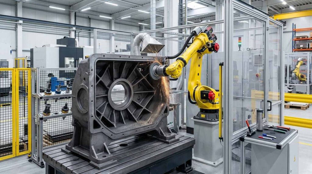
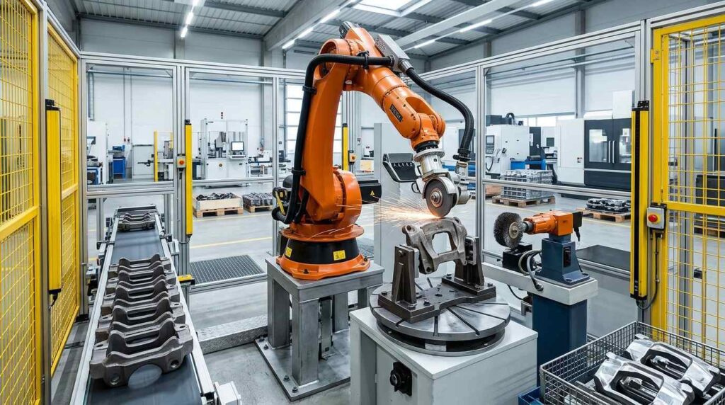
Crankshafts are critical rotating components used in engine systems, where they convert the reciprocating motion of pistons into rotational motion. As a typical shaft-type workpiece, a crankshaft includes main journals, crank pins, counterweights, fillet transition areas and end sections. During casting, forging and rough machining, common finishing problems include burrs, flash, sharp edges, rough surfaces and local residues around transition zones.
Traditional manual grinding is difficult to standardize, especially when operators need to process multiple journal transitions, fillet areas, end faces and local edge regions repeatedly. Different operators may apply different pressure and tool angles, which can lead to unstable finishing quality and over-grinding risks. This robotic grinding solution is designed for cast and forged crankshafts roughly 400–800 mm long with a swing circle typically under 250 mm, focusing on burr removal, fillet grinding, edge smoothing and surface cleaning before machining, assembly or final inspection.
What is a Crankshaft?
A crankshaft is a core rotating component in an internal combustion engine or power unit. It converts the linear motion of pistons into rotational output and transmits torque through the engine system. Depending on the design, crankshafts may be manufactured by casting, forging and subsequent machining, with precise journal surfaces, fillets and balance-related features. Forged steel dominates in high-load gasoline and diesel engines, while cast iron crankshafts appear mainly in large-bore diesel and cost-sensitive applications.
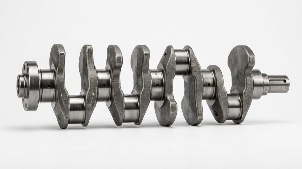
A typical crankshaft is a long shaft-type component with multiple journals, crank arms, transition fillets and end features. After casting or forging, it still requires finishing to remove burrs, flash, sharp edges and local surface residues before machining or assembly. The quality of these finishing operations affects machining preparation, surface consistency, balancing quality and final inspection.
| Item | Detalhes |
|---|---|
| Nome da peça | Crankshaft |
| Tamanho típico | Length commonly 400–800 mm by engine family; swing circle under ~250 mm |
| Material | Forged Steel / Cast Iron |
| Processo principal | Retificação robotizada |
| Processos assistidos | Deburring, Fillet Grinding, Surface Cleaning |
| Principais áreas de processamento | Journals, fillet transitions, crank arms, end faces, local edges, rough cast/forged surfaces |
| Gol da vitória | Remove burrs, flash and sharp edges while improving fillet and surface quality |
For this type of workpiece, the main requirement is not decorative polishing. The key task is to remove casting or forging defects, smooth critical fillet areas and clean local edges before further machining or assembly. For these repeated features, robotic grinding is the core process this solution is built on.
Typical Applications of Crankshafts
Crankshafts are used in engine and power systems where reciprocating motion must be converted into rotational motion. They are common in passenger vehicles, commercial vehicles, trucks, buses, industrial engines and other power units.
| Área de aplicação | Typical Function |
|---|---|
| Passenger Vehicle Engines | Convert piston motion into rotational output |
| Commercial Vehicle Engines | Provide torque transmission in heavy-duty engines |
| Truck Engines | Support high-load engine operation |
| Bus Engines | Used in durable powertrain systems |
| Industrial Engines | Applied in generators and power units |
| General Powertrain Systems | Used as a key rotating shaft component |
For these applications, burrs, flash and rough fillet areas are not just appearance issues. They may affect subsequent machining, balancing, assembly and final engine performance. A controlled robotic grinding process helps manufacturers achieve more repeatable finishing quality on shaft-type rotating components.
Pain Point Analysis of Crankshaft Finishing
Crankshafts present several finishing challenges. The first challenge is the long shaft structure. A crankshaft includes multiple journals, crank arms, transition fillets and end features that require consistent processing along the full length.
The second challenge is fillet and transition cleaning. Fillet areas are critical on crankshafts because they affect stress concentration and machining preparation. Burrs, flash or rough residues in these areas must be removed carefully.
The third challenge is local edge and end-face finishing. End sections, arm transitions and local edges may contain burrs or rough material after casting or forging. Manual processing can be inconsistent, especially in repeated batch production.
The fourth challenge is labor intensity and quality variation. Operators must repeatedly work on multiple similar features along a long part, which increases fatigue and makes quality control difficult.
| Problema comum | Área específica | Impacto |
|---|---|---|
| Burrs | Journals, arms, end faces | Affects machining and handling |
| Flash | Transition areas, edge boundaries | Reduces surface consistency |
| Arestas afiadas | Crank arms, end regions, local transitions | Creates handling risks |
| Fillet Roughness | Journal-to-arm transitions | Affects machining preparation |
| Variação manual | Long shaft and repeated features | Causes unstable finishing quality |
| Grinding Dust | Operação de retificação | Affects workshop environment and operator comfort |
Compared with manual grinding, robotic grinding provides a more controlled and repeatable process. The robot can follow programmed paths across repeated journal and fillet areas while maintaining stable tool contact and consistent finishing logic.
| Item de comparação | Esmerilhamento manual | Retificação robotizada |
|---|---|---|
| Long-Shaft Processing | Depende da habilidade do operador | Repeatable programmed path |
| Fillet Grinding | Easy to vary between operators | Stable and repeatable results |
| Burr Removal | Inconsistent on local edges | Targeted and consistent processing |
| Intensidade de mão de obra | High manual workload | Reduces repetitive grinding tasks |
| Process Consistency | Difficult to standardize | Programs can be saved and reused |
| Produção em lote | Limited by worker capacity | Suitable for repeated crankshaft models |
For crankshaft manufacturers, robotic grinding can transform repetitive finishing work into a more standardized process. It helps improve fillet consistency, reduce missed burrs and support stable batch production.
Robotic Grinding Process for Crankshafts
A robotic grinding cell for crankshafts can be configured according to workpiece size, material, burr condition, surface requirement and production volume. The system usually includes a six-axis industrial robot, dedicated fixture, abrasive grinding tool, flexible deburring tool, force-control or compliant mechanism, dust collection system and safety enclosure.
Because crankshafts are long, asymmetric and contain repeated journal and fillet regions, robot path planning is especially important. The system must process journals, transition fillets, crank arms and end sections while protecting critical machining surfaces.
| Etapa | Processo | Finalidade | Ferramenta / Sistema |
|---|---|---|---|
| 1 | Carregamento e posicionamento | Secure the crankshaft accurately | Dedicated fixture |
| 2 | Seleção de programas | Select the correct crankshaft model | HMI / robot program |
| 3 | Journal and Arm Edge Grinding | Remove flash and smooth local edges | Ferramenta de retificação abrasiva |
| 4 | Fillet Deburring | Remove burrs from fillet transitions | Ferramenta flexível para remoção de rebarbas |
| 5 | End Face Finishing | Smooth sharp edges on shaft ends | Rotary deburring tool / compliant tool |
| 6 | Surface Cleaning and Finishing | Improve local surface cleanliness and consistency | Abrasive belt or flexible grinding head |
| 7 | Controle de Qualidade | Check burr removal and edge condition | Inspeção manual ou visual |
| 8 | Descarregamento e limpeza | Remova a poeira e transfira a peça | Limpeza com jato de ar / aspiração |
Etapa 1: Carregamento e posicionamento
The crankshaft is placed into a dedicated fixture. The fixture should position the workpiece according to key reference journals or end surfaces and provide stable access to the journals, fillets, crank arms and end faces.
For repeated production, the fixture can be designed for stable clamping and efficient repositioning. If multiple crankshaft models are produced, model-specific fixtures or quick-change fixture solutions can be used.
Etapa 2: Seleção do programa
The operator selects the corresponding robot program according to the crankshaft model. Each model can have different paths, tool parameters and protected zones depending on journal layout and flash locations.
For higher automation requirements, barcode scanning, fixture recognition or visual positioning can be added to confirm the correct workpiece model.
Step 3: Journal and Arm Edge Grinding
The robot first processes the journal edges and crank arm transition areas. These areas often contain casting or forging flash, sharp edges and rough local boundaries. The robot follows the programmed path and removes unwanted material with an abrasive grinding tool.
Stable tool contact is important for this step. Force-controlled grinding helps maintain consistency and reduces the risk of over-grinding near precision surfaces.
Step 4: Fillet Deburring
After processing the main edges, the robot moves to the fillet transition areas between journals and crank arms. These zones are critical for shaft quality and require careful burr removal and surface conditioning.
The system can use a flexible deburring tool or smaller grinding head to process fillet areas. Proper path design helps ensure repeated burr locations are treated consistently.
Step 5: End Face Finishing
Crankshaft end faces and local shaft ends may contain burrs or rough edges after casting or forging. The purpose of this step is to smooth sharp edges and clean local boundaries without affecting critical dimensions.
The robot uses a compliant or rotary deburring tool to finish the end faces and local edges. This helps improve handling safety and downstream processing consistency.
Step 6: Surface Cleaning and Finishing
After edge grinding and fillet deburring, the robot can process selected shaft surfaces and local cast or forged zones to improve cleanliness and consistency. This step is especially useful before machining or assembly.
The process does not aim for mirror polishing. Instead, it removes small defects, local residues and visible irregularities to create a cleaner finished surface.
Etapa 7: Inspeção de qualidade
After grinding, the crankshaft is inspected for burr removal, fillet condition, surface cleanliness and over-grinding. Key inspection areas include journals, fillets, crank arm boundaries, end faces and visible shaft surfaces.

Inspection can be carried out manually, with gauges or with visual assistance depending on the plant’s quality standard.
Etapa 8: Descarregamento e limpeza
The finished crankshaft is removed from the fixture. Dust and grinding residues can be cleaned by air blowing, vacuum suction or brushing. The part can then move to machining, balancing, coating, packaging or the next production stage.
For larger production lines, the grinding cell can be integrated with conveyors, automatic loading and centralized dust collection.
Dificuldades e soluções na usinagem
Crankshafts are more demanding than simple shafts because they combine long length, multiple journals, fillet transitions and asymmetric arm sections. The robotic system must be designed for path accessibility, controlled fillet finishing, fixture stability and functional surface protection.
| Desafio | Causa | Solução robótica |
|---|---|---|
| Long-Shaft Accuracy | Multiple repeated features along the shaft length | Use programmed multi-section paths |
| Fillet Area Cleanup | Transition zones require careful deburring | Use flexible tools and localized paths |
| End Face Burrs | Local shaft ends retain flash and burrs | Use targeted end-face finishing tools |
| Proteção Funcional de Superfícies | Journal surfaces may be dimension-critical | Define protected zones and optimized paths |
| Geração de poeira | Cast/forged grinding creates fine particles | Use enclosed cell with dust extraction |
Difficulty 1: Processing Multiple Journals Along a Long Shaft
Crankshafts have multiple repeated journal areas along the shaft, which makes manual processing slow and inconsistent.
The solution is to divide the shaft into multiple programmed sections. A six-axis robot can maintain stable orientation and repeat the same sequence across batches.
Difficulty 2: Cleaning Critical Fillet Transitions
Fillet transitions are critical areas where burrs or rough residues can affect later machining and component quality. Manual operators may process these zones unevenly.
The solution is to use flexible deburring tools and carefully designed paths that follow the fillet geometry without damaging adjacent surfaces.
Difficulty 3: Finishing End Faces and Local Shaft Ends
End sections and local shaft ends often retain burrs after casting or forging. These areas may be missed during manual work.
The solution is to use rotary deburring tools or compliant grinding heads to process end faces consistently.
Difficulty 4: Protecting Machined Journal Surfaces
Some crankshaft surfaces may be precision machined or later machined, including journal zones and reference areas. These must not be damaged during grinding.
The solution is to define protected zones in the robot program and use accurate fixturing. Tool paths should avoid critical surfaces, and lower contact force can be used near sensitive regions.
Difficulty 5: Controlling Grinding Dust
Grinding cast or forged crankshafts generates fine dust and particles. Manual grinding exposes workers directly to the dust source and creates a harsher environment.
The solution is to use an enclosed robotic grinding cell with integrated dust collection. Local suction, protective covers and filtration systems help improve cleanliness and operator safety.
Application Scenario
Production Context
A powertrain component manufacturer produces cast and forged crankshafts for engine applications. The workpieces have multiple journals, fillet transitions, crank arms and end sections. Before automation, workers manually removed burrs, flash and sharp edges after casting or forging.
At higher volumes, hand finishing could not keep up with upstream output, so the priorities were consistent fillets, no missed burrs and less repetitive grinding work.
Desafios técnicos
The crankshaft had multiple burr-prone areas, including journal edges, fillet transitions, crank arm boundaries and end faces. Manual workers needed to constantly change tool angle and position, which caused unstable finishing quality.
Another challenge was protecting functional surfaces. Some journal areas had to remain dimensionally accurate after machining, so the robotic system needed to remove burrs and flash without affecting critical geometry. Dust was the third concern, because manual grinding on long shafts kept operators at the dust source all shift.
Solução
UBRIGHT SOLUTIONS designed a robotic grinding cell for cast and forged crankshafts. The system used a six-axis industrial robot, dedicated crankshaft fixture, abrasive grinding tool, flexible deburring tool and enclosed dust collection system.
The robot first processed the journal edges and crank arm boundaries, then removed burrs from the fillet transition areas and end faces. Controlled fillet-finishing paths were applied to transition zones. Protected zones were defined in the program to avoid damage to critical machined features.
| Item | Configuração |
|---|---|
| Peça de trabalho | Cast / Forged Crankshaft |
| Tamanho típico | Approx. 650 mm long, swing circle ≈ 190 mm |
| Processo principal | Retificação robotizada |
| Processo assistido | Deburring, Fillet Grinding, Surface Cleaning |
| Robô | Robô industrial de seis eixos |
| Ferramentas | Ferramenta de esmerilhamento abrasiva, ferramenta flexível para remoção de rebarbas |
| Calendário | Dedicated Crankshaft Fixture |
| Controle de poeira | Célula fechada com coleta de poeira |
| Inscrição | Journal Edge Grinding, Fillet Deburring, Flash Removal |
Outcome Overview
In a deployment of this type, finishing quality on journal edges and fillet transitions becomes more stable. Journals, transition zones and end sections are all covered by the saved program on every part.
The cell takes on the heavy grinding work, and because every shaft runs the same path, the process becomes standardized by design. The enclosure captures dust at the source.
| Área de Resultados | Melhoria |
|---|---|
| Fillet Consistency | More stable processing on journal-to-arm transitions |
| Burr Removal Quality | Fewer missed burrs around end faces and local edges |
| Surface Cleaning | More uniform cleaning of shaft surfaces |
| Redução da mão de obra | Redução da carga de trabalho manual repetitiva de esmerilhamento |
| Estabilidade da produção | Reusable robot programs for repeated crankshaft models |
| Controle de poeira | Enclosed cell improved workshop cleanliness |
PERGUNTAS FREQUENTES
Q1: Why is robotic grinding suitable for crankshafts?
Robotic grinding is suitable for crankshafts because they have multiple journals, fillet transitions and end sections that require consistent finishing. The robot can follow programmed paths and process the same areas repeatedly, making it suitable for batch production.
Q2: What defects can robotic grinding remove from crankshafts?
The system can remove burrs, flash, sharp edges and local surface residues. The most common processing areas include journals, fillet transitions, crank arm boundaries, end faces and visible shaft surfaces.
Q3: Can the robot process fillet transitions accurately?
Yes. With suitable path planning and flexible deburring tools, the robot can process fillet transitions and local edge areas. The final accessibility depends on the crankshaft geometry and tool selection.
Q4: Does a crankshaft need polishing?
In most cases, crankshafts do not require decorative mirror polishing. The main requirement is grinding, fillet cleaning, deburring and surface preparation before machining or assembly.
Q5: How does the robot avoid damaging functional journal surfaces?
The robot program can define protected zones and limit tool contact in precision areas. Proper fixturing, accurate positioning and controlled grinding force help protect critical surfaces and maintain dimensional consistency.
Q6: Can one robotic grinding cell process different crankshaft models?
Yes. A robotic grinding cell can process different crankshaft models if the fixtures and programs are designed properly. For similar product families, quick-change fixtures and saved programs can reduce changeover time.
Q7: What tools are used for crankshaft robotic grinding?
Common tools include abrasive grinding wheels, belt tools, flexible deburring heads, rotary deburring tools and compliant grinding tools. The final tool selection depends on journal layout, fillet size and finishing requirements.
Q8: Is dust collection necessary for crankshaft grinding?
Yes. Dust collection is strongly recommended. Grinding cast or forged crankshafts produces fine particles, so the robotic cell should include an enclosure, suction ports, dust collection pipes and filtration equipment.
Conclusão
Crankshafts are critical rotating components that require reliable finishing on journals, fillet transitions, crank arms and end sections. Burrs, flash, sharp edges and local surface residues can affect machining preparation, balancing quality, handling safety and final inspection results if they are not removed properly.
A robotic grinding solution helps crankshaft manufacturers improve fillet grinding, burr removal and surface cleaning in batch production. With dedicated fixtures, controlled tool paths, flexible deburring tools and integrated dust extraction, robotic finishing is well suited to repeated production of cast and forged crankshafts. For the cast structures that carry these shafts, see our balance shaft support robotic grinding solution.
If your crankshaft production still relies on manual fillet cleaning, journal edge grinding or burr removal, Entre em contato conosco for a customized robotic solution. Further engine-component finishing references are in the Automotivo e EV section and the Equipamentos catalog.