
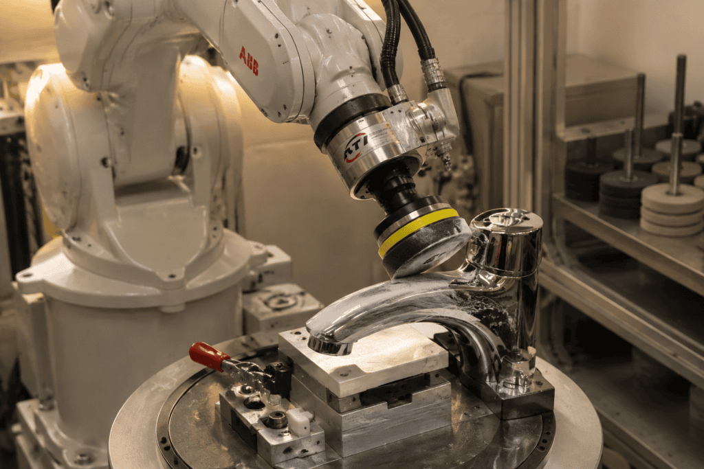
A robotic polishing machine is an industrial robot fitted with force control and polishing tooling—belt sanders, buffing wheels, pneumatic grinders—programmed to bring metal or plastic parts to a target surface finish, replacing manual polishing on repetitive, medium-to-high volume finishing work.
The definition hides a lot of engineering. Buyers who treat a polishing robot as “an arm with a buffer on the end” routinely end up with cells that burn parts, stall on throughput, or sit idle because nobody can reprogram them. This guide covers what goes into these systems, the two machine architectures, the seven selection factors, and where the money and lead time really go.
What Is a Robotic Polishing Machine, Precisely?
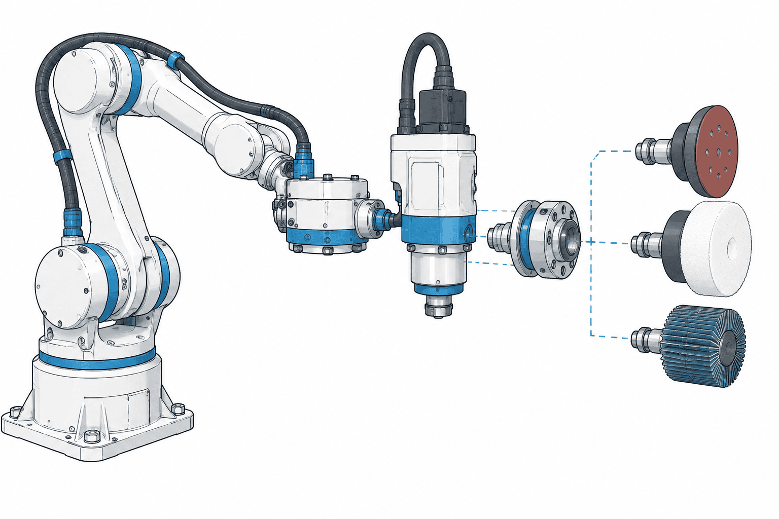
Strip away the marketing and a robotic polishing machine is a finishing cell built around one or more industrial robots. The robot moves either the abrasive tool or the workpiece along a controlled path while a force-control mechanism keeps the contact pressure between tool and surface inside a narrow band. A controller sequences the grit progression, manages tool and compound changes, and verifies surface roughness—commonly tracked as Ra in micrometers.
The reason manufacturers buy them is rarely “polish faster,” although robots usually do. The dominant motives are consistency and labor. Manual polishing quality swings with each operator’s skill, fatigue, and turnover; robot-polished part number 4,000 matches part number 40. It is also one of the dirtiest, most repetitive jobs on a factory floor—dust, vibration injuries, and chronic staffing shortages make it a natural automation target. A detailed overview of the full range of applications is on our robotic polishing solutions page.
One honest boundary up front: robotic polishing excels at production finishing—satin, brushed, and mirror finishes on engineered products. Ultra-precision optical mirror finishes below roughly Ra 0.05 µm, on lens molds or semiconductor components, still belong to dedicated ultra-precision polishing machines and a small population of master polishers. For abrasive stock removal on cast parts, see our robotic grinding guide. A robot is the right tool for the ten-thousandth faucet, not for a one-off optics-grade cavity.
What Goes Into a Robotic Polishing System
A workable cell is an assembly of subsystems, and the arm is often the least specialized part of it. Understanding each block lets you evaluate vendor proposals instead of comparing brand names.
1. The robot arm. Six-axis articulated robots dominate because polished surfaces are rarely flat—curved spouts, blended transitions, and multiple face angles demand full positional freedom. Reach and payload are selected against your part envelope and tooling weight, not the part weight alone. Smaller collaborative robots fit light-deburring and prototype work, but continuous polishing contact loads and dust push most production cells toward protected industrial arms.
2. Force control. The component that decides finish quality. Either a wrist-mounted force-torque sensor closing the loop with the robot controller, or an active compliance device between wrist and tool, keeps contact force steady as the surface pushes back. This topic deserves its own section below.
3. End-of-arm tooling. The business end, and the part vendors differ on most:
- Active belt sanders—motor-driven contact arms for grinding and heavy stock removal on castings and weld seams.
- Pneumatic random-orbit sanders—the workhorse for fine sanding and surface prep before buffing.
- Buffing and polishing wheels—cloth or sisal wheels carrying polishing compounds, used for the final luster pass.
- Radial compliance tools—tools with built-in spring or air suspension for forgiving contact on curved faces.
4. Tool changers. Automatic quick-changers let one robot run a coarse belt, switch to a fine sander, then pick up a buffing wheel mid-cycle. Without them, every grit change becomes a manual intervention and your lights-out ambitions end there.
5. Fixtures and workholding. Custom jigs that present the part to the robot the same way every time. Fixture repeatability becomes part-positioning error directly, and on thin-walled parts (sink basins, mid-frames) fixtures must also prevent chatter and deflection.
6. Part location and inspection. Laser finders or vision correct for part-to-part variation in casting batches; some cells add inline cameras to catch missed zones before parts ship.
7. The unglamorous periphery. Safety fencing or light curtains, dust extraction (polishing sludge is flammable and unhealthy), compound applicators, and part in/out conveyors or turntables. Periphery is frequently underestimated in budgeting and is often what separates a demo from a production cell.
Robot Holds the Tool vs. Robot Holds the Part
Every robotic polishing machine follows one of two architectures, and choosing between them is the most consequential design decision you will make.
Tool-in-hand (robot manipulates the tool, part is fixtured). The workpiece sits in a fixture, possibly on a two-axis positioner that rotates and tilts it, while the robot carries the sander or buffing wheel across the surface. This suits large or heavy parts—bathtubs, large panels, wheel hubs—and parts that need multi-face access. It also suits higher-mix production, since swapping a fixture and a program beats re-engineering a dedicated station. The trade-off is cycle time, because the robot must trace every square centimeter itself, and force-control quality depends on the wrist-side equipment.
Part-in-hand (robot manipulates the part against fixed stations). The robot picks the part from a tray or conveyor and presents it against stationary belt machines, buffing wheels, or polishing mops running at constant speed. This is the classic architecture for small, high-volume products—faucets, handles, cutlery, phone frames. Fixed abrasive stations can be large, powerful, and continuously dressed; one robot can serve several stations in sequence; and surface speed stays constant regardless of robot path quality. Its weakness is part-size and variety: each new part family needs new grippers, and very large parts exceed practical payload.
Mature integrators mix both: part-in-hand roughing against fixed belts, then a tool-in-hand cell for final buffing of complex curves. When you solicit proposals, ask which architecture the vendor recommends and why—a vendor who answers before asking about your parts is telling you something.
The 7 Selection Factors That Determine the Right Machine
Work through these in order before you talk pricing with anyone.
1. Part geometry complexity. Count the distinct surfaces, transitions, and interior pockets. Simple extruded or turned profiles can be finished on basic two-station cells (for long straight tube and bar, our pipe and tube polishing machine guide covers the centerless alternative); deep cavities, undercut faces, and tight internal radii drive up axes, tooling variety, and programming hours—and occasionally make robotic finishing uneconomic versus a dedicated machine.
2. Material. Brass, stainless steel, aluminum, zinc alloy, hardened steel, titanium, and plastics each demand different abrasives, forces, and wheel speeds. Brass and aluminum cut easily and tolerate compliant tooling; stainless needs higher force and stiffer setups; zinc die castings bring porosity issues that no polisher can hide. State your full material list at the RFQ stage, including incoming surface condition—polishing cannot fix a bad casting.
3. Takt time requirements. Start from required parts per hour and work backward through cycle time, load/unload time, and changeovers. Be realistic: a robot tracing complex curves with a force-controlled tool is not dramatically faster per part than a skilled worker—its advantage is that it never slows down, never takes breaks, and can run three shifts. If you need a genuine tenfold throughput jump, the answer is usually parallel stations or part-in-hand architecture, not a faster robot.
**4. Consistency and finish specification. Define the target in measurable terms—Ra band, gloss units, scratch direction—and how you will verify it. “Same as the sample” is not a specification, and vendors cannot quote against it. Where consistency requirements are moderate, passive compliance tooling is often enough; tight Ra bands across blended curves generally require closed-loop force control.
5. Changeover frequency. If you run one part in millions, invest in hard fixtures and optimized cycle time. If your factory runs fifty SKUs in small lots, prioritize quick-change tooling, parametric programs, and offline programming capability—otherwise reprogramming cost quietly eats the automation savings.
6. Floor space and utilities. A single-station cell can fit in a 3×3 m footprint with standard power and air. Multi-station cells with conveyors, dust collection, and fencing consume serious floor area and may need three-phase power and compressed air upgrades. Export buyers should also confirm voltage standards and CE/UL documentation early.
7. Budget band. Roughly: entry single-station cells commonly run $80,000–150,000 USD; fully engineered multi-station production cells with vision, changers, and turnkeys commonly land in the mid six figures; high-end multi-robot lines exceed that again. Set the band before quoting so integrators design to it—and remember the arm is often only 20–40% of the total.
Force Control: The Technology That Separates Good Cells from Bad Ones
Polishing is a contact process, and contact processes fail without controlled force. A robot in pure position control follows its programmed path exactly—but the real world intervenes: castings vary by a millimeter, belts wear mid-cycle, parts deflect under load, and the robot’s own repeatability error shows up as force spikes. Position-only robots on polishing duty produce uneven gloss, burn marks on high spots, and missed lows.
Active (closed-loop) force control mounts a force-torque sensor at the wrist and measures contact force in real time, with controller loops correcting the tool path hundreds of times per second. The robot stops tracking a position and starts tracking a force target—typically held within a tolerance of roughly ±1–5 N for fine polishing and buffing, with higher forces for grinding passes. Active control maintains even pressure across curves, tolerates part variation, and produces the consistent Ra values that manual polishing cannot guarantee across shifts.
Passive compliance takes the opposite approach: springs, air cylinders, or compliant materials between tool and mount absorb variation mechanically. No sensor loop, no tuning—cheaper, simpler, and genuinely effective on forgiving tasks like flat-surface sanding or rough deburring. But a passive device has one force profile; when geometry changes sharply, it cannot adapt.
The practical selection rule: passive compliance for simple geometry and tolerant finishes; active force control whenever curves, blends, or tight finish bands are involved. If a proposal for complex 3D parts shows no force-torque sensor or active compliance device, treat that as a red flag regardless of how attractive the price is.
Programming and the Offline Programming Question
On conventional machine tools, the program is a deliverable. In robotic polishing, programming is an operating cost you will pay repeatedly, so evaluate it as a selection criterion.
Teach programming—an engineer jogging the robot through the path point by point—is still how most cells are commissioned. It needs no software investment, but a complex part can consume days per surface, and the cell is down while it happens.
Offline programming (OLP) software builds tool paths from the part’s 3D model, simulates them against the real cell geometry, and downloads ready programs. For high-mix production it transforms changeover economics: a new variant becomes a CAD import and an afternoon, not a week of downtime. The trade-off is license cost, a steeper engineering skill requirement, and a simulation-to-reality gap that still needs on-site fine-tuning—OLP reduces teach time, it does not eliminate it.
Newer tools add path generation from scanned part data and sensor-driven correction. Ask each vendor three questions: programming hours per new variant, what happens to production during a changeover, and whether the quoted scope includes operator training. The answers predict cost of ownership better than any spec sheet.
Where Robotic Polishing Proves Itself: Typical Applications
The technology has matured in specific product families where volumes are high and finishes are commercial, not optical.
Sanitary hardware. Brass faucets are the archetypal case—curved spouts, multiple transitions, mirror chrome prep, produced in volumes that justify dedicated cells. Our brass faucet robotic polishing solutions page details the station layout and grit progression. Stainless steel sinks add a wrinkle: large thin-walled panels where deflection control matters as much as the polish itself; see stainless steel sink polishing.
Architectural hardware. Door handles and luxury trim parts combine aesthetic finishes with high SKU counts—a natural fit for quick-change part-in-hand cells, as covered in our luxury door handle polishing solution write-up.
Consumer electronics. Smartphone and tablet mid-frames need edge deburring and fine surface blending at volumes manual lines cannot sustain, with finish specs tight enough to require active force control. The smartphone mid-frame polishing and deburring solutions page covers that workflow.
Automotive wheels and components. Alloy wheels pair heavy forgings with cosmetic curved faces; multi-stage alloy wheel robotic polishing lines handle the sequence from lathe finishing through final buffing. If you run a wheel refinishing or manufacturing operation, our wheel polishing machine guide compares all five equipment formats.
Robotic Cell vs. Five-Axis CNC Polishing vs. Dedicated Machines
Robots are not the only automated option, and the alternatives sometimes win.
| Criterion | Robotic polishing cell | Five-axis CNC polishing | Dedicated polishing machine |
|---|---|---|---|
| Geometry flexibility | High—reprogram for new parts | High, with tight precision | One part family only |
| Positional precision | Moderate (sub-mm) | Very high | Fixed by mechanism |
| Force capability | Controlled, moderate | Machine-driven, high | Often passive |
| Changeover | Hours (fixtures + program) | CAM reprogramming | Mechanical retooling |
| Best fit | Curved, cosmetic, mid-to-high volume | Precision surfaces, tight tolerances | Millions of identical parts |
| Cost behavior | Mid capex, flexible | High capex | Low unit cost at extreme volume |
Five-axis CNC-based polishing delivers precision a robot cannot match and suits small, tightly toleranced components. Dedicated rotary or transfer polishing machines beat robots on unit cost when you genuinely will run one part design for years. The robotic cell occupies the flexible middle—and for export-oriented manufacturers whose product mix shifts with customer demand, that middle is where most real buyers land.
Cost Structure and Lead Time: What You Are Actually Paying For
Quotations confuse buyers because the arm everyone recognizes is a minority of the price. A realistic breakdown of a turnkey cell:
- Robot arm and controller—commonly 20–40% of the cell
- End-of-arm tooling, force control, and tool changers—15–25%
- Fixtures, stations, structure, guarding—15–25%
- Integration engineering, programming, and commissioning—15–30%
- Periphery: dust extraction, safety, conveyors, documentation—10–20%
That is why two cells built on the same arm can differ by a factor of three in price. Scrutinize the engineering line: under-scoped programming and commissioning is the most common cause of cells that arrive but never reach rated output.
On ranges rather than point numbers: entry-level single-station cells for simple parts generally start in the $80,000–150,000 USD range; engineered multi-station cells with vision and automatic changers run into the mid-to-high six figures; multi-robot lines are project-priced. Lead time from purchase order to acceptance typically spans three to six months, with the schedule driven less by the robot and more by fixture design, tooling procurement, and the FAT/SAT test cycles. Ask every bidder what is excluded—spare tooling, site preparation, operator training, and shipping are the usual gaps between a headline number and a landed cost.
Frequently Asked Questions
What is a robotic polishing machine?
An automated finishing system in which an industrial robot—equipped with force control, abrasive or buffing tooling, and part fixtures—performs the sanding, buffing, and polishing operations that were previously done by hand. A complete machine includes the cell safety, dust management, and control software needed to run unattended in production, not just the arm.
How much does a robotic polishing machine cost?
It depends on scope more than brand. Simple single-station cells start in the $80,000–150,000 USD range, engineered multi-station cells with vision and tool changers commonly reach the mid-to-high six figures, and multi-robot lines are quoted per project. Robot hardware is typically 20–40% of the total; tooling, fixtures, engineering, and commissioning make up the rest. Compare quotations line by line on those blocks, not on the total.
What materials can it polish?
The commercially proven list covers brass, bronze, copper, stainless steel, carbon steel, aluminum and its alloys, zinc die castings, titanium, and hard plastics/composites. Each material dictates its own abrasive grades, contact forces, and wheel speeds, so the practical question for a vendor is not “can you polish this material” but “how many cells like mine, in this material, are running today.”
How accurate and consistent is robotic polishing?
Positional repeatability of a six-axis arm is in the sub-0.1 mm class, but polishing quality is governed by force consistency, not position alone. With closed-loop force control holding contact pressure within roughly ±1–5 N, robotic cells hold finish quality part after part far tighter than manual lines. The honest limit: ultra-precision optical finishes below about Ra 0.05 µm remain the territory of dedicated ultra-precision machines and specialist polishers.
Robotic vs. manual polishing—what actually changes?
Throughput per station improves moderately; the larger gains are in consistency (no shift-to-shift variation), scrap reduction, labor exposure (dust, vibration, repetitive strain), and the ability to run unattended shifts. Costs move from ongoing wages to upfront capital and occasional reprogramming. Most facilities also report quality-floor improvement: the robot never has a bad Monday, so the worst part in a batch gets much better.
Choosing Well, in Summary
Selecting a robotic polishing machine is mostly an exercise in self-knowledge: defining your parts, materials, takt, and changeover reality precisely enough that integrators can engineer to them instead of guessing. Get the architecture decision (tool-in-hand vs. part-in-hand) right, insist on proper force control for curved cosmetic surfaces, budget for programming as a recurring cost rather than a one-time fee, and read quotations against the cost structure above. Do that, and the technology reliably delivers what it promises—consistent finish quality at production volumes, without depending on a shrinking pool of skilled polishers.
If you are evaluating a specific part family—faucets, sinks, handles, 3C components, wheels—UBright Solutions engineers robotic polishing and deburring cells around your parts, not around a catalog. Send us your part drawings, target finish, and monthly volumes, and we will come back with an architecture recommendation and a scoped quotation.

