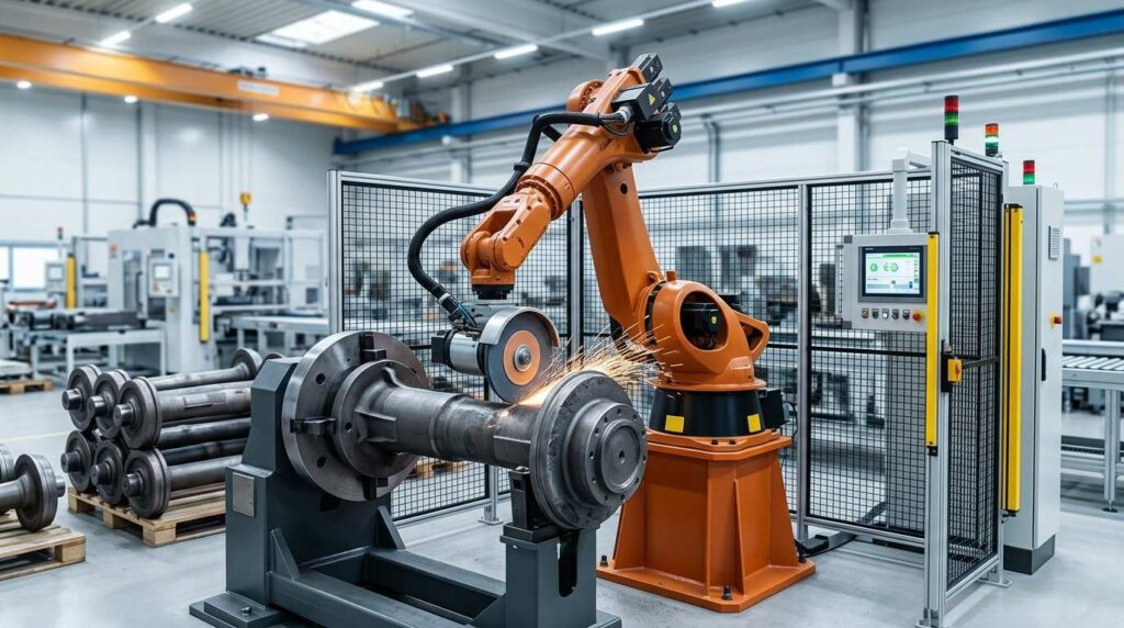
Flywheel housings are cast structural components used in engine and drivetrain systems around the flywheel connection area. A typical workpiece is a relatively shallow, irregular cast housing with a central circular opening, multiple outer contour edges, rib-reinforced surfaces and several mounting holes. During casting and machining, common finishing problems include flash on contour edges, burrs around holes and openings, sharp transition boundaries and local surface residues on visible cast areas.
Traditional manual grinding is time-consuming and difficult to standardize, especially when operators need to repeatedly process irregular outer contours, center opening edges, hole mouths, rib intersections and thin-wall surface areas. Different operators may apply different pressure and tool angles, which often leads to unstable finishing quality and over-grinding risks. This robotic grinding solution is designed for cast flywheel housing components roughly in the 500 mm footprint class, focusing on contour edge grinding, hole deburring, rib transition cleaning and surface preparation before coating, assembly or final inspection.
What is a Flywheel Housing?
A flywheel housing is a cast component used around the flywheel area of an engine or drivetrain assembly. It provides structural connection, mounting support and protective coverage for related rotating and transmission-side parts. Depending on product design, the housing may connect with the engine block, transmission section, clutch-related parts or other powertrain interfaces.
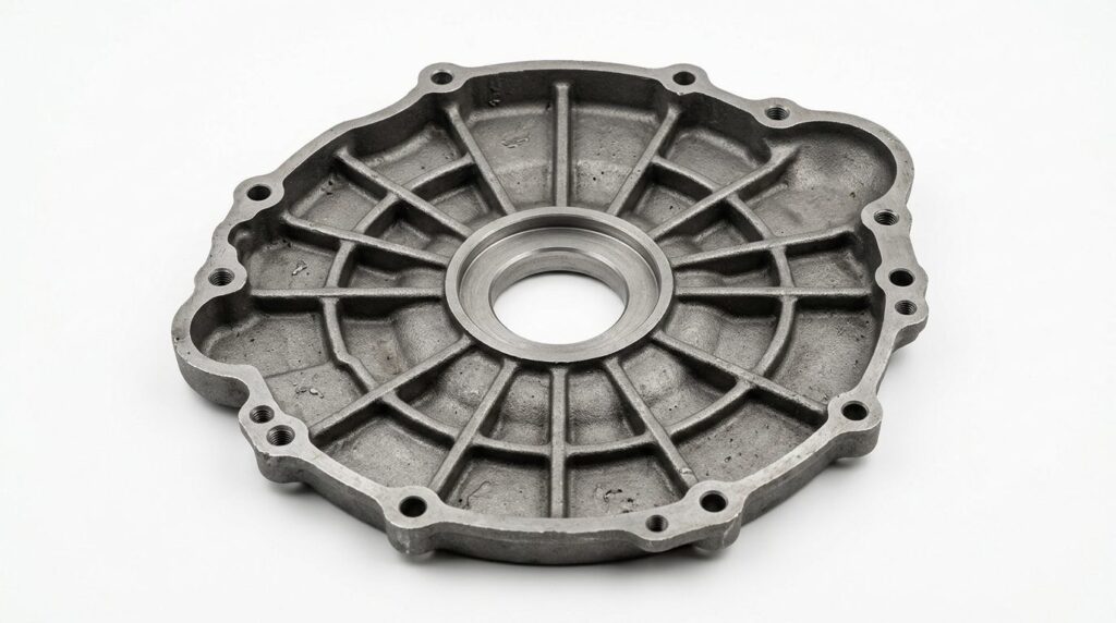
This type of flywheel housing is not a deep cylindrical casing, but a relatively shallow and irregular cast housing with a central opening, outer contour boundaries, ribbed reinforcement and multiple hole features. After casting and machining, this type of part still requires finishing to remove flash, burrs, sharp edges and local surface residues before coating, assembly or shipment.
| 項目 | 詳細 |
|---|---|
| ワークピース名 | Flywheel Housing |
| 典型的なサイズ | Varies by engine family; commonly 400–600 mm footprint, shallow depth |
| 素材 | Cast Iron / Cast Aluminum |
| 主なプロセス | ロボット研削 |
| アシストプロセス | Deburring, Edge Rounding, Surface Cleaning |
| 主な加工エリア | Outer contour edges, central opening, mounting holes, rib intersections, parting lines, visible cast surfaces |
| ゴール | Remove casting flash, burrs, sharp edges and surface residues on the housing structure |
For this type of workpiece, the main requirement is not decorative polishing. The key task is to remove casting defects, deburr hole mouths and opening edges, smooth contour boundaries and improve surface cleanliness before coating or assembly. The core process of this solution is therefore ロボット研削 rather than manual finishing.
Typical Applications of Flywheel Housings
Flywheel housings are used in engine and drivetrain systems where structural connection, mounting accuracy and enclosure around the flywheel area are required. Although the exact shape may vary, these parts generally serve as mounting and transition components between major powertrain sections.
| アプリケーションエリア | 代表的な機能 |
|---|---|
| Engine Systems | Provide structure around the flywheel connection zone |
| Transmission Interfaces | Connect engine-side and transmission-side assemblies |
| 商用車 | Support durable powertrain housing structures |
| Trucks and Buses | Used in heavy-duty drivetrain connection systems |
| Industrial Power Units | Applied in engine coupling and drive assemblies |
| General Powertrain Casting | Used as an irregular cast housing with multiple mounting interfaces |
For these applications, burrs, sharp edges and local surface residues are not only appearance problems. They may also affect assembly fit, handling safety, coating quality and final inspection. A controlled robotic grinding process helps manufacturers achieve more repeatable finishing quality on irregular cast housing parts.
Pain Point Analysis of Flywheel Housing Finishing
Flywheel housings present several finishing challenges. The first challenge is the irregular contour. This workpiece includes non-uniform outer edges, a central opening, multiple holes, rib transitions and thin-wall areas that are difficult to process consistently by hand.
The second challenge is hole and opening deburring. Burrs often remain around the central opening, bolt holes and local cutouts after casting or machining. If these burrs are not removed properly, they may affect assembly, edge safety or inspection results.
The third challenge is surface cleaning and flash removal. Visible cast surfaces, rib intersections and contour boundaries may contain residual flash, parting lines or local roughness. Manual grinding can remove these defects, but the result depends heavily on operator experience.
The fourth challenge is labor intensity. Operators need to repeatedly process many edge transitions and local areas on a relatively thin and irregular workpiece. This increases fatigue and makes quality consistency difficult to control.
| よくある問題 | 特定地域 | インパクト |
|---|---|---|
| キャスティング・フラッシュ | Outer contour edges, parting lines, local boundaries | Affects appearance and assembly preparation |
| Hole Burrs | Central opening, bolt holes, cutouts | May interfere with assembly or inspection |
| シャープなエッジ | Outer contours, openings, rib transitions | 安全な取り扱いのリスクを生む |
| Surface Residues | Visible cast surfaces and rib intersections | Reduces coating and cleaning consistency |
| マニュアル・バリエーション | Edge and hole areas | Causes unstable finishing quality |
| Grinding Dust | 研磨作業 | 作業場の環境と作業者の快適性に影響 |
Compared with manual grinding, robotic grinding provides a more controlled and repeatable process. The robot can follow programmed paths across irregular contours, hole locations and rib transitions while maintaining stable tool contact.
| 比較項目 | 手動研磨 | ロボット研削 |
|---|---|---|
| Contour Edge Grinding | オペレーターの技量による | Repeatable programmed path |
| Hole and Opening Deburring | Easy to miss local burrs | Targeted and consistent processing |
| Surface Cleaning Consistency | Varies between operators | Stable and repeatable finishing |
| 労働強度 | High manual workload | Reduces repetitive grinding tasks |
| Process Consistency | Difficult to standardize | プログラムの保存と再利用が可能 |
| バッチ生産 | Limited by worker capacity | Suitable for repeated housing models |
For flywheel housing manufacturers, robotic grinding can transform repetitive finishing work into a more standardized process. It helps improve contour consistency, reduce missed burrs and support stable batch production.
Robotic Grinding Process for Flywheel Housings
A robotic grinding cell for flywheel housings can be configured according to workpiece size, material, burr condition, contour complexity and production volume. The system usually includes a six-axis industrial robot, dedicated fixture, abrasive grinding tool, flexible deburring tool, force-control or compliant mechanism, dust collection system and safety enclosure.
Because housings of this type are shallow, irregular castings rather than deep cylindrical casings, robot path planning must focus on outer contour edges, opening boundaries, hole mouths, rib intersections and visible surface zones. The system must process these areas while protecting critical machined features.
| ステップ | プロセス | 目的 | ツール/システム |
|---|---|---|---|
| 1 | ローディングとポジショニング | Secure the flywheel housing accurately | 専用フィクスチャー |
| 2 | プログラム選択 | Select the correct housing model | HMI / robot program |
| 3 | Contour Edge Grinding | Remove flash and smooth outer edges | 研磨工具 |
| 4 | Opening and Hole Deburring | Remove burrs from openings and hole mouths | Flexible deburring tool / rotary tool |
| 5 | Rib Transition Finishing | Smooth rib intersections and local boundaries | Compliant grinding tool |
| 6 | Surface Cleaning and Finishing | Improve local surface cleanliness and consistency | Abrasive belt or flexible grinding head |
| 7 | 品質検査 | Check burr removal and edge condition | 手動または目視検査 |
| 8 | 荷降ろしと清掃 | 埃を取り除き、部品を移す | エアブロー/バキュームクリーニング |
ステップ1:積み込みと位置決め
The flywheel housing is placed into a dedicated fixture. The fixture should position the workpiece according to key reference surfaces and provide stable access to contour edges, hole groups, the central opening and rib intersections.
For repeated production, the fixture can be designed for quick positioning and stable clamping. If multiple housing models are produced, model-specific fixtures or quick-change fixture solutions can be used.
ステップ2:プログラムの選択
The operator selects the corresponding robot program according to the flywheel housing model. Each model can have different paths, tool parameters and protected zones depending on shape and burr locations.
For higher automation requirements, barcode scanning, fixture recognition or visual positioning can be added to confirm the correct workpiece model.
Step 3: Contour Edge Grinding
The robot first processes the major outer contour edges of the flywheel housing. These areas often contain casting flash, parting lines and sharp boundaries. The robot follows the programmed path and removes unwanted material with an abrasive grinding tool.
Stable tool contact is important for this step. Force-controlled grinding helps maintain consistency and reduces the risk of over-grinding near functional regions.
Step 4: Opening and Hole Deburring
After processing the main edges, the robot moves to the central opening, bolt holes, mounting holes and local cutouts where burrs often remain. These areas require targeted tool access and repeatable path control.
The system can use a flexible deburring tool, rotary tool or smaller grinding head to process hole mouths and opening edges. Proper path design helps ensure repeated burr areas are treated consistently.
Step 5: Rib Transition Finishing
Housings of this type include ribbed reinforcement and local contour transitions. These intersections may retain flash, sharp boundaries or local roughness after casting.
The robot uses a compliant grinding tool to smooth rib intersections and local transitions. The goal is controlled edge conditioning and surface cleanup, not heavy material removal.
Step 6: Surface Cleaning and Finishing
After edge grinding and hole deburring, the robot can process selected cast surfaces, rib areas and visible local zones to improve surface cleanliness and consistency. This step is especially useful before painting or coating.
The process does not aim for decorative polishing. Instead, it removes small surface defects, residual flash and visible irregularities to create a cleaner finished surface.
ステップ7:品質検査
After grinding, the flywheel housing is inspected for burr removal, edge condition, surface cleanliness and over-grinding. Key inspection areas include contour edges, the central opening, bolt holes, rib intersections and visible cast surfaces.

Inspection can be carried out manually, with gauges or with visual assistance depending on the plant’s quality standard.
ステップ8:荷下ろしと清掃
The finished flywheel housing is removed from the fixture. Dust and grinding residues can be cleaned by air blowing, vacuum suction or brushing. The part can then move to coating, assembly, packaging or the next production stage.
For larger production lines, the grinding cell can be integrated with conveyors, automatic loading and centralized dust collection.
機械加工の困難と解決策
Flywheel housings of this type are more demanding than simple flat castings because they combine irregular contours, a central opening, multiple holes and ribbed reinforcement features. The robotic system must be designed for path accessibility, controlled edge finishing, fixture stability and functional surface protection.
| チャレンジ | 原因 | ロボットソリューション |
|---|---|---|
| Irregular Outer Contours | Non-uniform edge paths and multiple turning points | Use programmed multi-section contour grinding paths |
| Opening and Hole Burrs | Burrs remain around the center opening and hole groups | Use targeted deburring tools and local tool access |
| Rib Transition Cleanup | Rib intersections retain flash and roughness | Use compliant finishing paths at rib junctions |
| Functional Surface Protection | Some mounting faces and machined areas must be preserved | Define protected zones and optimized paths |
| ダストジェネレーション | Cast grinding creates fine particles | Use enclosed cell with dust extraction |
Difficulty 1: Processing Irregular Contour Edges
A housing of this type has multiple contour turns, local protrusions and non-uniform boundary paths. Manual grinding of these areas is slow and difficult to standardize.
The solution is to divide the contour into multiple programmed path sections. A six-axis robot can maintain stable orientation and repeat the same sequence across batches.
Difficulty 2: Deburring the Central Opening and Hole Groups
Burrs often remain around the central opening, bolt hole groups and small cutouts. Manual operators may miss local burrs or process them unevenly.
The solution is to use flexible deburring tools or smaller grinding heads that can access local hole and opening features. The robot can approach these areas from predefined angles and repeat the same sequence for every part.
Difficulty 3: Cleaning Rib Intersections Without Over-Grinding
Rib transitions often need local finishing, but excessive grinding may change the part’s visual consistency or remove too much material from thin-wall areas.
The solution is to use compliant tools and defined transition-finishing paths. This helps maintain consistent edge quality and surface cleanup without over-processing.
Difficulty 4: Protecting Functional Surfaces
Some flywheel housing areas may be machined or dimension-critical, including mounting surfaces, hole seats or contact regions. These must not be damaged during grinding.
The solution is to define protected zones in the robot program and use accurate fixturing. Tool paths should avoid critical surfaces, and lower contact force can be used near sensitive regions.
Difficulty 5: Controlling Grinding Dust
Grinding cast flywheel housings generates fine dust and particles. Manual grinding exposes workers directly to the dust source and creates a harsher environment.
The solution is to use an enclosed robotic grinding cell with integrated dust collection. Local suction, protective covers and filtration systems help improve cleanliness and operator safety.
Application Scenario
Production Context
A powertrain casting manufacturer produces cast flywheel housings for engine and transmission assembly applications. The workpieces have irregular outer contours, a central opening, multiple bolt holes, rib reinforcement and several local transition areas. Before automation, workers manually removed casting flash, burrs and sharp edges after casting and machining.
As batches grew, hand finishing fell behind the machining output, so the priorities became consistent contour edges, no missed burrs around holes and openings, and less repetitive grinding work.
技術的課題
The flywheel housing had multiple burr-prone areas, including outer contour edges, the central opening, bolt hole groups, rib intersections and parting line areas. Manual workers needed to constantly change tool angle and position, which caused unstable finishing quality.
Another challenge was protecting functional surfaces. Some areas had to remain dimensionally accurate after machining, so the robotic system needed to remove burrs and flash without affecting critical assembly geometry. Dust control was a further requirement, since manual stations could not contain the fine particles generated on every part.
ソリューション
UBRIGHT SOLUTIONS designed a robotic grinding cell for cast flywheel housings. The system used a six-axis industrial robot, dedicated housing fixture, abrasive grinding tool, flexible deburring tool and enclosed dust collection system.
The robot first processed the major contour edges and parting line areas, then removed burrs from the central opening, bolt holes and local cutouts. Controlled transition-finishing paths were applied to rib intersections and local boundaries. Protected zones were defined in the program to avoid damage to critical machined features.
| 項目 | 構成 |
|---|---|
| ワークピース | Cast Flywheel Housing |
| 典型的なサイズ | Approx. 500 mm class shallow housing |
| 主なプロセス | ロボット研削 |
| アシストプロセス | Deburring, Edge Rounding, Surface Cleaning |
| ロボット | 産業用6軸ロボット |
| 工具 | 研磨工具、フレキシブルバリ取り工具 |
| 備品 | Dedicated Flywheel Housing Fixture |
| ダストコントロール | 集塵機付密閉セル |
| 申し込み | Contour Edge Grinding, Hole Deburring, Surface Cleaning |
Outcome Overview
In a deployment of this type, finishing quality on contour edges, openings and rib transitions becomes measurably more stable. Outer edges, hole groups and local features are processed from the same saved program on every part.
The cell absorbs the heavy manual grinding work, and every part follows an identical verified path, which is what makes the process standardized. Dust stays inside the enclosure instead of the workshop.
| 結果エリア | 改善 |
|---|---|
| Contour Edge Consistency | More stable processing on irregular outer edges |
| Opening and Hole Deburring | Fewer missed burrs around the central opening and bolt holes |
| Transition Finishing Quality | More uniform rib and contour transition condition |
| 労働力削減 | Reduced repetitive manual grinding workload |
| 生産の安定性 | Reusable robot programs for repeated housing models |
| ダストコントロール | 密閉されたセルが作業場の清潔さを向上 |
よくあるご質問
Q1: Why is robotic grinding suitable for flywheel housings?
Robotic grinding is suitable for flywheel housings because they have irregular contour edges, openings, holes and rib transitions that require consistent finishing. The robot can follow programmed paths and process the same areas repeatedly, making it suitable for batch production.
Q2: What defects can robotic grinding remove from flywheel housings?
The system can remove casting flash, parting lines, burrs, sharp edges and local surface irregularities. The most common processing areas include contour edges, the central opening, bolt holes, rib intersections and visible cast surfaces.
Q3: Can the robot process opening edges and hole mouths?
Yes. With suitable path planning and flexible deburring tools, the robot can process opening edges, bolt holes, mounting holes and other local burr-prone areas. The final accessibility depends on the geometry of the housing and tool selection.
Q4: Does a flywheel housing need polishing?
In most cases, flywheel housings do not require decorative mirror polishing. The main requirement is grinding, deburring, edge conditioning and surface cleaning before coating or assembly.
Q5: How does the robot avoid damaging functional surfaces?
The robot program can define protected zones and limit tool contact in precision areas. Proper fixturing, accurate positioning and controlled grinding force help protect critical surfaces and maintain dimensional consistency.
Q6: Can one robotic grinding cell process different flywheel housing models?
Yes. A robotic grinding cell can process different housing models if the fixtures and programs are designed properly. For similar product families, quick-change fixtures and saved programs can reduce changeover time.
Q7: What tools are used for flywheel housing robotic grinding?
Common tools include abrasive grinding wheels, belt tools, flexible deburring heads, rotary deburring tools and compliant grinding tools. The final tool selection depends on contour accessibility, burr size and finishing requirements.
Q8: Is dust collection necessary for flywheel housing grinding?
Yes. Dust collection is strongly recommended. Grinding cast housings produces fine particles, so the robotic cell should include an enclosure, suction ports, dust collection pipes and filtration equipment.
結論
Flywheel housings of this type are shallow and irregular cast housing components that require reliable finishing on outer contour edges, the central opening, bolt holes, rib intersections and visible cast surfaces. Casting flash, burrs, sharp edges and local surface residues can affect assembly consistency, handling safety, coating quality and final inspection results if they are not removed properly.
A robotic grinding solution helps flywheel housing manufacturers improve contour edge grinding, hole deburring and surface cleaning in batch production. With dedicated fixtures, controlled tool paths, flexible deburring tools and integrated dust extraction, robotic finishing is well suited to repeated production of cast flywheel housings. For the rotating parts these housings enclose, see also our crankshaft robotic grinding solution.
If your flywheel housing production still relies on manual contour edge grinding, opening deburring or surface cleaning, お問い合わせ for a customized robotic solution. Related powertrain finishing systems are listed under Automotive Parts, and full machine specifications are in the 設備 catalog.