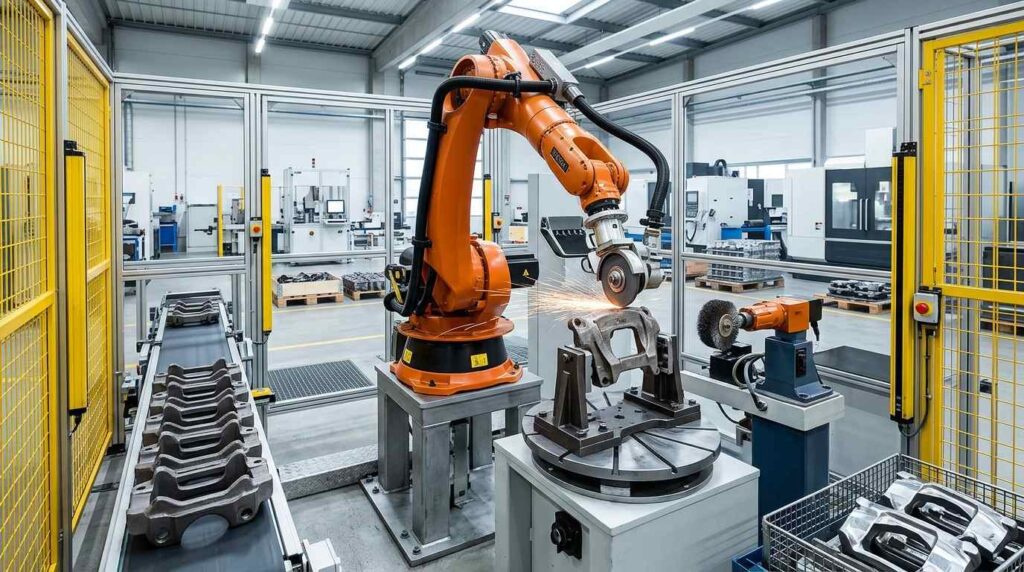
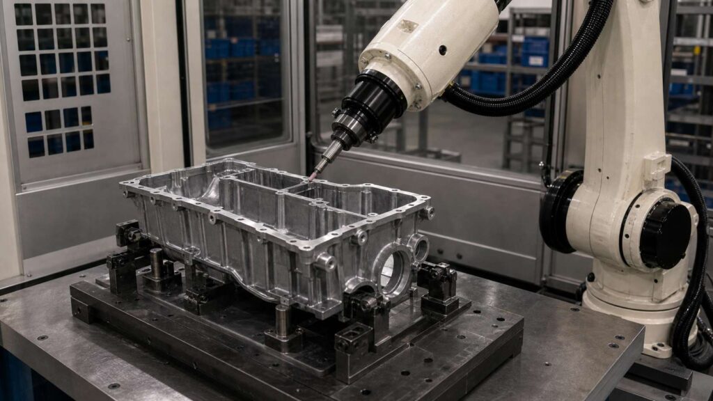
Aluminum alloy engine lower frames are structural casting components used in automotive engine lower assemblies, crankcase systems and powertrain support structures. In its common form, this part has a long lower-frame body, large internal openings, perimeter edges, sealing-area boundaries, multiple small holes, reinforced ribs and local pockets, making edge deburring more complex than on simple plate-like castings.
This robotic edge deburring solution is designed for aluminum alloy engine lower frames with typical dimensions around 450–700 mm in length, depending on the engine model. It helps remove burrs, sharp edges, light flash and trimming residues from long perimeter edges, window openings, hole edges, rib transitions and sealing-adjacent boundaries while improving edge consistency and reducing manual deburring workload.
What Is an Aluminum Alloy Engine Lower Frame?
An aluminum alloy engine lower frame is a cast structural component located around the lower part of an engine assembly. It is commonly used to reinforce the engine bottom structure, connect with surrounding components and provide mounting, sealing or support interfaces for engine-related systems.

Structurally, the workpiece follows a wide lower-frame layout with long edge boundaries, large internal windows, several holes, rib networks, pocket areas and contour lines near sealing or mounting regions. After casting and trimming, burrs and sharp edges may remain around the long perimeter, window openings, small holes, rib edges and cavity transitions. For this type of workpiece, the main finishing requirement is robotic edge deburring, edge rounding and local cleanup rather than heavy grinding or decorative polishing.
| 項目 | 詳細 |
|---|---|
| ワークピース名 | Aluminum Alloy Engine Lower Frame |
| 典型的なサイズ | Around 450–700 × 250–450 × 80–180 mm, depending on model |
| 素材 | アルミニウム合金鋳造 |
| 主なプロセス | Robotic Edge Deburring |
| アシストプロセス | Edge Rounding, Light Flash Removal, Local Surface Cleanup |
| 主要な処理分野 | Long perimeter edges, internal window edges, hole openings, rib edges, pocket boundaries, sealing-adjacent contours |
| 保護地域 | Sealing surfaces, mounting faces, precision holes, machined pads, fitting interfaces |
| ゴール | Remove sharp edges, burrs and light flash while maintaining stable edge quality and protecting functional surfaces |
Typical Finishing Challenges of Aluminum Alloy Engine Lower Frame
An aluminum alloy engine lower frame is challenging because its quality requirement is concentrated on many edge boundaries rather than one heavy grinding area; the machine categories suited to this duty are compared in our deburring machine types guide. Long perimeter edges, internal windows, small holes and rib transitions all require controlled edge deburring, but the tool must not touch nearby sealing surfaces or machined interfaces.
Manual edge deburring can be inconsistent because operators need to follow long contour lines and frequently change posture around windows, holes and ribs. Some edges may remain sharp, while others may be over-rounded. For aluminum alloy parts, excessive pressure may also leave visible marks or remove material near important sealing or mounting areas.
| よくある問題 | 特定地域 | インパクト |
|---|---|---|
| シャープなエッジ | Long perimeter, window openings, holes | 取り扱いや組み立てのリスクが生じる |
| Light Flash / Trimming Residues | Outer contour, cutout edges, local pockets | Affects edge consistency and appearance |
| Residual Burrs | Rib edges, hole openings, internal corners | Causes unstable finishing quality |
| Uneven Edge Rounding | Repeated long contours and window boundaries | Leads to inconsistent edge feel and quality |
| マニュアル・バリエーション | Multiple small holes, long edges and ribs | Produces different results between operators |
| Sensitive Sealing Areas | Sealing rails, mounting faces, machined pads | Risk of damage during manual deburring |
Robotic Edge Deburring Process for Aluminum Alloy Engine Lower Frame
A robotic edge deburring cell for aluminum alloy engine lower frames should be designed around edge tracking, controlled tool compliance, fixture stability and protected-surface management. The goal is not heavy stock removal, but stable burr removal and controlled edge rounding along many long and local edge features. Dual-station layouts such as our 5-axis dual-station deburring equipment let one side be unloaded and reloaded while the other is finished.

For engine lower frames with typical dimensions around 450–700 mm in length, the process usually includes loading, program selection, protected-area confirmation, perimeter edge deburring, window edge deburring, hole edge treatment, rib and pocket edge finishing, inspection and unloading. Flexible deburring tools, chamfering tools and small finishing tools can be combined according to edge type.
| ステップ | プロセス | 目的 | ツール/システム |
|---|---|---|---|
| 1 | ローディングとポジショニング | Secure the lower frame for stable edge access | 専用フィクスチャー |
| 2 | プログラム選択 | Match the correct part model and edge path | HMI / ロボットプログラム |
| 3 | 保護区域の確認 | Define sealing, mounting and precision no-touch zones | 試合日程のロジック/プログラム設定 |
| 4 | Long Perimeter Edge Deburring | Remove sharp edges and light flash from outer contour | フレキシブルなバリ取りツール |
| 5 | Internal Window Edge Deburring | Process large cutout and window boundaries | Compliant deburring tool |
| 6 | Hole Opening Edge Treatment | Deburr small holes and mounting openings | Chamfering tool / Deburring spindle |
| 7 | Rib and Pocket Edge Finishing | Clean local rib edges and recessed transitions | Small finishing head |
| 8 | Sealing-Adjacent Edge Control | Deburr near sealing contours without touching sealing faces | Controlled path / No-grind zones |
| 9 | 品質検査 | Check edge consistency and protected areas | 手動または目視検査 |
| 10 | 荷降ろしと清掃 | Remove chips and transfer the workpiece | Air blow / Vacuum cleaning |
ステップ1:積み込みと位置決め
The aluminum alloy engine lower frame is placed into a dedicated fixture that supports the casting from stable non-critical areas. Since the workpiece has long edges, large openings and relatively thin rib structures, stable positioning is important for consistent edge contact.
The fixture should allow the robot to access the perimeter, window edges, hole openings and pocket areas without repeated repositioning. Good positioning accuracy also helps maintain a safe distance from sealing surfaces and machined pads.
ステップ2:プログラムの選択
With the frame clamped, the right program for that casting is called up at the HMI. This matters when one cell runs several lower frame variants with different edge paths, hole layouts or rib patterns.
The selected program defines the edge sequence, tool angle, feed speed, tool compliance and protected zones. Saved paths help maintain consistent edge quality across repeated batches.
Step 3: Protected Area Confirmation
Before deburring starts, the system confirms which areas must remain untouched. For an engine lower frame, protected surfaces usually include sealing rails, machined pads, mounting faces, precision holes and fitting interfaces.
This step is essential because many burrs are located near sealing-adjacent boundaries. The robot should clean the edge itself while avoiding contact with the flat sealing surface or machined reference area.
Step 4: Long Perimeter Edge Deburring
The long perimeter edge is one of the main processing areas on the engine lower frame. Light flash, trimming residues and sharp edges may remain along the outer contour after casting and rough cleanup.
A flexible deburring tool can follow the long edge path and apply controlled contact pressure. The robot removes burrs and creates a more consistent edge condition without changing the overall part profile.
Step 5: Internal Window Edge Deburring
Large internal windows and cutouts create long inner edge boundaries. These areas are easy to touch during handling and may also affect assembly preparation if burrs remain.
A compliant deburring tool can follow the internal window profile and clean straight edges, corner transitions and narrow sections. Compared with manual deburring, the robot can keep a more stable tool angle around repeated window features.
Step 6: Hole Opening Edge Treatment
The engine lower frame includes multiple small holes, mounting holes and local openings. Burrs around these features may interfere with bolt insertion, assembly seating or downstream inspection.
Driven by the robot, a chamfering tool or spindle hits every hole opening with the same depth and angle, which keeps the bolt pattern uniform and cuts out manual rework.
Step 7: Rib and Pocket Edge Finishing
Rib edges and recessed pockets are local areas where small burrs can remain. These burrs are often missed in manual processing because the features are located between structural ribs or inside pocket boundaries.
A small finishing head can access these local edges and remove residual burrs. The robot can divide the frame into several local zones and process rib and pocket edges with stable posture.
Step 8: Sealing-Adjacent Edge Control
Some edges are close to sealing contours or machined flat surfaces. These areas require more careful path control than ordinary outer edges because the tool must not scratch or over-round the functional surface.
The robot uses controlled tool orientation and no-grind zones to deburr only the edge boundary. This helps maintain sealing surface integrity while removing sharp edges and small burrs nearby.
Step 9: Quality Inspection
After robotic edge deburring, operators inspect the perimeter edges, internal windows, hole openings, rib edges, pocket boundaries and sealing-adjacent areas. The inspection confirms that sharp edges have been removed and that protected surfaces remain clean and undamaged.

Visual inspection can be combined with manual touch checks, sample edge gauges or camera-based inspection depending on production requirements. Inspection results can also support path optimization and tool life control.
Step 10: Unloading and Cleaning
After inspection, the engine lower frame is unloaded and transferred to the next process. Aluminum chips and dust should be removed from holes, pockets, windows and rib areas.
An enclosed robotic cell with chip and dust collection is recommended for aluminum edge deburring. It helps reduce loose particles, improve cleanliness and lower the operator’s exposure to repetitive manual deburring work.
機械加工の困難と解決策
| チャレンジ | 原因 | ロボットソリューション |
|---|---|---|
| Long Perimeter Edge Consistency | Large frame body creates long edge paths | Programmed edge-following deburring |
| Internal Window Sharp Edges | Large openings retain burrs along inner contours | Compliant tool path around window profiles |
| Hole Edge Variation | Multiple small holes require repeated edge treatment | Chamfering or deburring spindle routine |
| Sealing-Area Protection | Edge burrs may be close to sealing surfaces | No-touch zones and controlled tool angle |
| Rib and Pocket Burrs | Local structural details create hidden burrs | Small finishing tool and divided local zones |
| Aluminum Over-Deburring Risk | Soft aluminum can be marked or over-rounded | Controlled pressure and suitable tool compliance |
Difficulty 1: Maintaining Consistent Long Edge Quality
The engine lower frame has long perimeter edges that are difficult to deburr evenly by hand. Manual processing may leave some sections sharp while over-rounding other areas.
The solution is to use a programmed edge-following path with a flexible deburring tool. The robot keeps stable tool contact along the long contour, improving edge consistency across the full frame.
Difficulty 2: Internal Window Edge Deburring
Large cutouts and windows create inner edge boundaries with straight sections, corners and narrow transitions. Burrs around these areas can remain if the operator cannot maintain a stable tool angle.
The solution is to use a compliant deburring path around each window profile. The robot follows the internal contour and removes sharp edges with controlled pressure.
Difficulty 3: Repeated Hole Opening Treatment
The part contains many small holes and mounting openings. Each hole requires consistent edge treatment, but manual chamfering can vary from one position to another.
The solution is to use a chamfering tool or deburring spindle with repeated robotic routines. The robot approaches each hole with the same angle and depth, improving repeatability.
Difficulty 4: Deburring Near Sealing Boundaries
Some burrs are located near sealing rails, gasket boundaries or machined pads. These areas are sensitive because scratches or over-removal may affect sealing or assembly performance.
The solution is to define sealing surfaces as protected zones and control the tool posture near edge boundaries. The robot removes burrs from the edge without contacting the functional sealing surface.
Difficulty 5: Local Rib and Pocket Burr Removal
Ribs and pockets create small edge locations that are easy to miss during manual deburring. These residual burrs may appear minor but can affect handling quality and final inspection.
The solution is to use a small finishing tool and divide local features into separate processing zones. The robot processes each rib edge and pocket boundary with repeatable posture and controlled contact.
Application Scenario
Scenario Background
Picture a casting line feeding aluminum engine lower frames into a manual finishing bench: workers walk each part around its long perimeter edges, internal windows, small holes, rib edges and pocket boundaries, knocking down sharp edges, light flash and burrs by hand.
As monthly output rises, that workflow gets harder to keep uniform: long edges stay sharp in places, and sealing-adjacent zones pick up tool marks. Plants in this position usually move the work to a robotic edge deburring cell to lock in edge consistency, ease the manual burden and protect functional surfaces.
技術的課題
The part brings long outer contours, large internal windows, dozens of small holes, reinforced ribs and local pocket features. Most defects are not heavy residues but repeated small burrs and sharp edges spread across many edge locations.
Edge consistency is the crux. The process must clean long and local edges while avoiding over-rounding, excessive removal or scratches near sealing surfaces and machined interfaces.
ソリューション
For this duty, the cell pairs a six-axis industrial robot with a dedicated lower-frame fixture and an edge-focused tool set: a flexible deburring tool for the long perimeter, a compliant tool for internal windows, a chamfering tool for small holes and a small finishing head for ribs and pocket edges.
Sealing surfaces, machined pads, mounting faces and precision holes sit inside no-touch zones, so the robot only works the edge boundaries with controlled tool angle and contact pressure. Chip and dust extraction inside the enclosure keeps the finishing area clean.
| 項目 | 構成 |
|---|---|
| ワークピース | Aluminum Alloy Engine Lower Frame |
| 典型的なサイズ | Around 450–700 × 250–450 × 80–180 mm, depending on model |
| 主なプロセス | Robotic Edge Deburring |
| アシストプロセス | Edge Rounding, Light Flash Removal, Local Surface Cleanup |
| ロボット | 産業用6軸ロボット |
| 工具 | Flexible deburring tool, compliant deburring tool, chamfering tool, small finishing head |
| 備品 | Dedicated Engine Lower Frame Support Fixture |
| Protection Strategy | Protected sealing surfaces, machined pads, mounting faces and precision holes |
| ダストコントロール | Enclosed Cell with Aluminum Chip and Dust Collection |
実施結果
The robotic cell took over repetitive edge deburring work on long perimeter contours, internal windows, small holes, rib edges, pocket boundaries and sealing-adjacent edges. People on the line move to loading, unloading, inspection and tool maintenance; the repetitive deburring burden falls away and batch results even out.
The edge-focused process also reduced the risk of over-processing. Instead of relying on manual feel, the robot followed saved edge paths with controlled pressure, helping maintain a more consistent edge condition across the engine lower frame.
| 結果エリア | 改善 |
|---|---|
| Perimeter Edge Quality | More consistent edge condition along long outer contours |
| Window Edge Deburring | Stable cleanup around large internal openings |
| Hole Edge Treatment | Repeatable deburring around small holes and mounting openings |
| Sealing-Area Protection | Lower risk of scratches near sealing and machined surfaces |
| Rib and Pocket Cleanup | Reduced missed burrs in local structural features |
| Edge Consistency | More stable edge rounding across repeated batches |
| 労働力削減 | Reduced repetitive manual edge deburring workload |
| 生産の安定性 | Saved programs for repeated engine lower frame models |
| Workshop Environment | Cleaner finishing area with enclosed aluminum chip collection |
Information Needed for a Robotic Grinding Proposal
To recommend a suitable robotic edge deburring cell for your aluminum alloy engine lower frame, we usually need the part drawing, material grade, casting weight, photos of burrs, flash or sharp edges, required edge deburring areas, protected sealing or machined surfaces, current manual deburring cycle time and annual production volume.
Our engineers use these inputs to weigh fixture design, robot reach, tool choice, chip extraction layout and overall feasibility. For aluminum alloy engine lower frames, it is especially important to identify which edges require deburring and which sealing surfaces, machined pads or precision holes must be protected during robotic processing.
よくあるご質問
Q1: Is this workpiece an engine lower frame?
Yes. The part described here is an aluminum alloy engine lower frame, with a broad frame body, long perimeter edges, internal windows, small holes, ribs and pocket boundaries.
Q2: Why is robotic edge deburring suitable for this workpiece?
Robotic edge deburring is suitable because the part has many repeated long and local edge features. A robot can follow programmed edge paths with controlled pressure, improving consistency compared with manual deburring.
Q3: What areas can the robot deburr on an engine lower frame?
The robot can deburr long perimeter edges, internal window edges, small hole openings, rib edges, pocket boundaries, local cutouts and sealing-adjacent edge areas. The exact processing range should be confirmed according to the drawing and actual burr distribution.
Q4: Does this part need heavy grinding or polishing?
In most cases, this part does not need heavy grinding or decorative polishing. The main requirement is edge deburring, edge rounding, light flash removal and local cleanup.
Q5: How are sealing surfaces protected during edge deburring?
Sealing surfaces are protected through fixture positioning, robot path planning and no-touch zones in the program. The robot processes only the nearby edge boundary while avoiding contact with the sealing face or machined pad.
Q6: Can one robotic cell handle similar lower frame models?
Yes. One robotic cell can often handle similar aluminum alloy engine lower frame models if the fixture, tool access and robot reach are designed for part variation. Different edge programs can be saved for different models or part numbers.
結論
Aluminum alloy engine lower frames have long perimeter edges, internal windows, small holes, ribs, pockets and sealing-adjacent contours, making manual edge deburring difficult to standardize. A robotic edge deburring solution helps manufacturers remove sharp edges, burrs and light flash while improving edge consistency and protecting key functional surfaces. For a heavier transmission-side casting in the same family, see our large aluminum alloy engine gear housing deburring and grinding solution.
If your engine lower frame production still relies on manual perimeter deburring, window edge cleanup or hole-edge treatment, お問い合わせ for a customized robotic solution. More casting-specific references are collected under 自動車・EV, and the hardware behind them is listed in 設備.