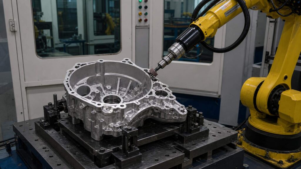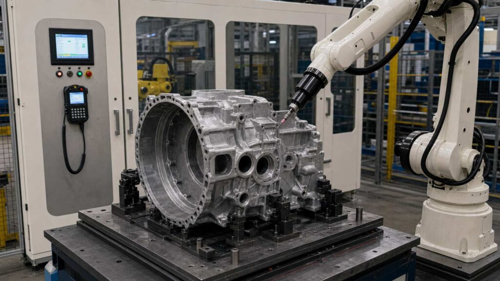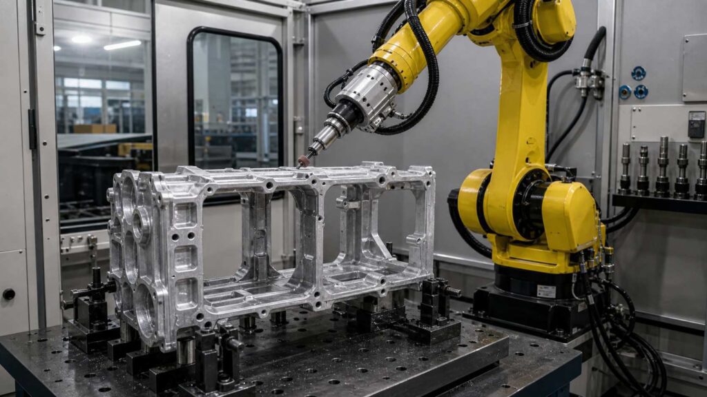
Aluminum alloy cylinder block skirt frames are structural casting components used in automotive engine and powertrain systems. This part includes a large open frame structure, multiple window openings, mounting holes, reinforced ribs, bosses, outer flanges and recessed cavity areas, making post-casting deburring and grinding more difficult than simple aluminum castings.
This robotic deburring and grinding solution is designed for aluminum alloy cylinder block skirt frames with typical dimensions around 400–600 mm in length, depending on the specific engine model. It helps remove burrs, casting flash, parting lines, sharp edges and gate residues from window openings, outer contours, mounting holes, rib transitions and recessed cavity edges while improving finishing consistency and reducing manual grinding workload.
What Is an Aluminum Alloy Cylinder Block Skirt Frame?
An aluminum alloy cylinder block skirt frame is a structural casting used around the lower engine block or crankcase support area. It helps reinforce the engine structure, support bearing-related areas and connect with other powertrain components through mounting holes, flanges and fitting surfaces.

The workpiece has a rectangular open-frame layout with large internal windows, dense reinforcing ribs, multiple bolt holes, raised bosses and irregular outer contours. After casting and trimming, burrs, flash, parting lines, gate residues or sharp edges may remain around the window edges, outer perimeter, hole openings, rib roots and cavity transitions. For this type of workpiece, the main finishing requirement is robotic deburring, local grinding and edge rounding rather than decorative polishing.
| Artikel | Einzelheiten |
|---|---|
| Name des Werkstücks | Aluminum Alloy Cylinder Block Skirt Frame |
| Typische Größe | Around 400–600 × 250–400 × 80–180 mm, depending on model |
| Material | Aluminiumguss |
| Hauptprozess | Entgraten und Schleifen mit Robotern |
| Unterstützte Prozesse | Kantenverrundung, Entgraten, lokale Oberflächenbearbeitung |
| Wichtige Verarbeitungsbereiche | Outer contour, window openings, mounting holes, rib transitions, boss edges, recessed cavity edges, gate-cut areas |
| Schutzgebiete | Mounting faces, sealing surfaces, bearing-related interfaces, precision holes, machined fitting areas |
| Fertigstellung des Ziels | Remove burrs, flash, parting lines, gate residues and improve finishing consistency |
Typical Finishing Challenges of Aluminum Alloy Cylinder Block Skirt Frame
An aluminum alloy cylinder block skirt frame is more difficult to finish than a simple flat casting because it contains many open windows, narrow rib structures, hole groups, bosses and functional surfaces. Burrs are not concentrated in one area but distributed across outer edges, internal openings, rib intersections, hole boundaries and recessed transitions.
Manual deburring can be inconsistent because operators must frequently change tool posture and grinding pressure. The thin rib areas and internal window edges are easy to miss, while functional surfaces close to burr areas may be damaged if the operator applies excessive force. Since aluminum alloy is softer than cast iron, over-grinding may also cause unwanted tool marks or local material removal.
| Gemeinsames Problem | Spezifischer Bereich | Auswirkungen |
|---|---|---|
| Gussgrate / Trennfugen | Outer contour, frame perimeter, flange edges | Beeinflusst die Konsistenz und das Erscheinungsbild der Kanten |
| Gate-Rückstände | Gate-cut positions around the casting body or flange area | Erfordert einen stärkeren lokalen Materialabtrag |
| Scharfe Kanten | Window openings, mounting holes, outer edges | führt zu Risiken bei der Handhabung und Montage |
| Restgrate | Rib roots, boss edges, recessed cavity transitions | Führt zu einer schwankenden Verarbeitungsqualität |
| Manuelle Variation | Repeated window edges, hole groups and rib transitions | Dies führt zu uneinheitlichen Ergebnissen bei den verschiedenen Anwendern |
| Sensible Funktionsbereiche | Mounting faces, sealing surfaces, bearing-related interfaces, precision holes | Beschädigungsgefahr beim manuellen Schleifen |
Robotic Deburring and Grinding Process for Aluminum Alloy Cylinder Block Skirt Frame
A robotic deburring and grinding cell for aluminum alloy cylinder block skirt frames should be designed around fixture stability, multi-angle accessibility, controlled contact force and protected-surface control. The process must remove burrs, flash, parting lines and gate residues from the complex frame structure while avoiding damage to mounting faces, sealing surfaces and precision fitting areas. To compare robot cells with dedicated machine formats for this kind of work, see our deburring machine types guide.
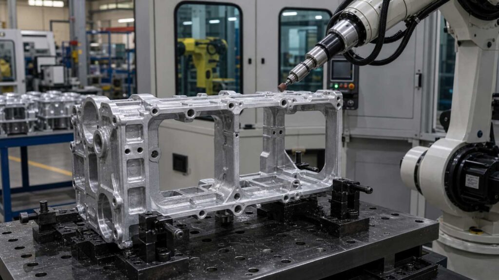
For aluminum alloy cylinder block skirt frames with typical dimensions around 400–600 mm in length, the process usually includes workpiece positioning, program selection, protected-area confirmation, outer contour grinding, window and hole edge deburring, rib transition finishing, quality inspection and unloading. Different tools may be used for different areas, including abrasive grinding tools, flexible deburring tools, chamfering tools and small grinding heads.
| Schritt | Prozess | Zweck | Werkzeug/System |
|---|---|---|---|
| 1 | Laden und Positionieren | Secure the workpiece for stable access | Dedizierte Halterung |
| 2 | Programmauswahl | Match the correct model and path | HMI / Roboterprogramm |
| 3 | Bestätigung des Schutzgebiets | No-Grind-Zonen und geschützte Schnittstellen definieren | Spielplanlogik / Programmeinstellungen |
| 4 | Outer Contour Grinding | Remove flash and parting lines from frame edges | Schleifwerkzeug |
| 5 | Window and Hole Edge Deburring | Remove burrs from internal openings and mounting holes | Flexible deburring tool / Chamfering tool |
| 6 | Endbearbeitung von Rippen- und Vorsprungsübergängen | Process rib roots, bosses and recessed transitions | Kleiner Schleifkopf / Nachgiebiges Werkzeug |
| 7 | Qualitätskontrolle | Grate entfernen und geschützte Bereiche überprüfen | Manuelle oder visuelle Prüfung |
| 8 | Entladung und Reinigung | Remove dust and transfer the workpiece | Luftblasen / Staubsaugen |
Schritt 1: Laden und Positionieren
The aluminum alloy cylinder block skirt frame is loaded into a dedicated fixture that supports the casting from stable non-critical areas. Because the workpiece has large open windows, thin ribs and an irregular outer profile, stable clamping is important to prevent vibration during deburring and grinding.
The fixture should allow the robot to reach the outer contour, internal window edges, mounting holes and rib transitions without repeated manual repositioning. Good positioning accuracy also helps the robot maintain a safe distance from protected mounting faces and machined interfaces.
Schritt 2: Programmauswahl
Once the frame is clamped, the matching program is selected at the HMI. This is what lets one cell run several skirt frame models with different window shapes, hole positions or rib layouts.
The selected program defines the tool path, processing order, robot posture, tool speed, feed rate and protected zones. Saved programs help improve repeatability and reduce dependence on operator experience during repeated production batches.
Schritt 3: Bestätigung des geschützten Bereichs
Before the robot starts grinding, the system confirms which areas must not be touched by the abrasive tool. For a cylinder block skirt frame, protected areas usually include mounting faces, sealing surfaces, precision holes, bearing-related interfaces and machined fitting surfaces.
This step is critical because many burrs are located very close to functional areas. The robot should remove burrs from edge boundaries and local transitions while avoiding contact with surfaces that affect assembly accuracy or sealing performance.
Step 4: Outer Contour Grinding
The robot first processes the outer contour of the skirt frame, where casting flash, trimming marks and parting line residues are commonly found. These edges may include straight sections, curved corners, local protrusions and flange transitions.
An abrasive grinding tool can follow the programmed contour path and remove raised defects from repeated edge areas. For aluminum alloy castings, grinding pressure should be controlled to avoid cutting into the base material or creating deep tool marks on the casting surface.
Step 5: Window and Hole Edge Deburring
The large internal windows and multiple mounting holes are major deburring areas on this workpiece. Burrs around these openings can create handling risks and may affect downstream assembly or machining preparation.
A flexible deburring tool or chamfering tool can be used to process the window edges and hole openings. The robot should approach each edge with the correct tool angle, especially around narrow windows, round holes and irregular cutouts. This allows the cell to remove sharp edges while maintaining the original geometry of the aluminum casting.
Step 6: Rib and Boss Transition Finishing
The reinforced ribs, raised bosses and recessed cavity transitions are more difficult to process than exposed outer edges. Burrs often remain at rib roots, boss boundaries and narrow corner areas where manual operators may miss small defects.
Local features like rib roots and boss corners are handled with small-diameter grinding heads or compliant tools. The robot can divide the inner structure into several processing zones and finish each rib or boss transition with repeatable posture. This improves consistency in areas where manual deburring is usually unstable.
Schritt 7: Prüfung der Qualität
After robotic deburring and grinding, the operator checks the outer contour, window openings, mounting holes, rib transitions, boss edges and gate-cut areas. The check verifies that every window and hole edge is clean and that machined faces show no tool contact.

On high-volume lines a camera system can take over the first-pass check while operators sample-audit the rest, and over time the inspection data feeds back into tool life planning, path compensation and local process parameters.
Schritt 8: Entladen und Reinigen
After inspection, the finished cylinder block skirt frame is unloaded and transferred to the next production process. Aluminum chips, dust and fine particles should be removed from window openings, hole edges and recessed cavity areas.
An enclosed robotic cell with dust collection is recommended for aluminum alloy grinding and deburring. It helps reduce airborne dust, improve workshop cleanliness and create a more controlled finishing environment than open manual grinding.
Bearbeitungsschwierigkeiten und Lösungen
| Herausforderung | Ursache | Robotische Lösung |
|---|---|---|
| Long Outer Contour Flash | Large frame perimeter creates repeated flash and parting line areas | Programmed contour grinding path |
| Window Edge Burrs | Large internal openings retain sharp casting and trimming edges | Flexibles Entgraten entlang von Fensterprofilen |
| Hole and Boss Burrs | Multiple mounting holes and bosses create repeated edge defects | Chamfering or local deburring routine |
| Rib Root Burrs | Reinforced ribs and narrow transitions are difficult to access | Small tool access and divided local finishing zones |
| Funktionaler Oberflächenschutz | Mounting, sealing and bearing-related areas must not be damaged | Protected zones excluded from grinding paths |
| Empfindlichkeit gegenüber Aluminium | Aluminum alloy can be over-ground or marked by excessive force | Controlled force, proper abrasive selection and compliant tooling |
Difficulty 1: Long and Irregular Outer Contour
The aluminum alloy cylinder block skirt frame has a long outer perimeter with straight edges, curved corners, local protrusions and flange transitions. Flash and parting line residues often appear along these areas after casting and trimming.
The solution is to use a programmed robotic contour-grinding path. This allows the robot to follow the irregular frame boundary with stable tool contact while reducing manual variation and avoiding unnecessary material removal from the aluminum casting.
Difficulty 2: Large Window Opening Edge Burrs
These castings include large internal window openings that create long inner edge boundaries. These edges often retain burrs or sharp corners, especially around window intersections and narrow internal transitions.
The solution is to use a flexible deburring tool with controlled contact pressure. The robot can follow each window profile and remove burrs from the inner edge without changing the original opening shape or damaging nearby rib structures.
Difficulty 3: Multiple Mounting Holes and Boss Edges
Cylinder block skirt frames usually contain many mounting holes, raised bosses and local circular features. Burrs around these areas may affect assembly preparation, bolt seating or handling safety.
The solution is to use a chamfering tool, flexible deburring spindle or small abrasive tool for local hole-edge treatment. The robot can process repeated holes with the same approach angle and tool depth, improving consistency across the whole workpiece.
Difficulty 4: Rib Roots and Recessed Transitions
Reinforced ribs are important structural features, but they also create narrow intersections and recessed corners. Burrs at rib roots are difficult for manual operators to reach consistently, especially when the rib direction changes across the frame.
The solution is to divide the rib structure into local finishing zones. A small grinding head or compliant deburring tool can access rib roots and corner transitions with controlled posture, reducing missed burrs in hidden areas.
Difficulty 5: Protecting Functional Surfaces
The skirt frame includes mounting faces, sealing surfaces, precision holes and bearing-related interfaces that must not be damaged during grinding. These functional areas may be close to burr-prone edges, making manual finishing risky.
The solution is to define no-grind zones in the robot program and fixture reference system. The robot removes burrs from the surrounding edge areas while keeping the tool away from protected interfaces that affect assembly accuracy.
Application Scenario
Production Context
A skirt frame is essentially a frame made of edges: the outer perimeter, several large window openings, and dozens of holes all need the same treatment, inside and out. Manual deburring means working both sides of the frame, changing posture at every window, and keeping the force light near the bearing and sealing areas.
At engine-component volumes, that combination of repetition and precision is where manual results start to scatter, and it is the usual trigger for moving the part to a robotic cell.
What Slows Manual Finishing Down
The windows are the main issue. Each large opening has a long inner edge that is awkward to reach with a hand tool, and burrs concentrate exactly where the rib intersections meet the window boundary. Exposed outer edges, by contrast, are easy to reach, and easy to over-grind, so one operator typically finishes the outer contour quickly and thoroughly while the window interiors receive uneven attention.
Gate stubs on the frame add a second process mode, since they need heavier removal than the edge work happening nearby, and all of it has to happen without visible marks on the alloy.
How the Cell Is Set Up
The usual configuration is a six-axis industrial robot with a tool set split by feature: an abrasive grinding tool for outer contour flash and parting lines, a flexible deburring tool for the window openings, a chamfering tool for the hole pattern, and a small grinding head for rib roots and boss transitions. Dual-station equipment, such as our six-axis dual-station deburring machine, suits this part family well, since one frame can be loaded while another is being finished.
The fixture holds the frame in one stable position that leaves both outer and inner edges reachable, protected surfaces are registered as no-grind zones, and the cell runs enclosed with extraction for aluminum chips and grinding dust.
| Artikel | Konfiguration |
|---|---|
| Werkstück | Aluminum Alloy Cylinder Block Skirt Frame |
| Typische Größe | Around 400–600 × 250–400 × 80–180 mm, depending on model |
| Hauptprozess | Entgraten und Schleifen mit Robotern |
| Unterstützter Prozess | Kantenverrundung, Entgraten, lokale Oberflächenbearbeitung |
| Roboter | Sechsachsiger Industrieroboter |
| Werkzeugbau | Abrasive grinding tool, flexible deburring tool, chamfering tool, small grinding head |
| Halterung | Dedicated Cylinder Block Skirt Frame Support Fixture |
| Schutzstrategie | Protected mounting faces, sealing surfaces, precision holes and bearing-related interfaces |
| Staubkontrolle | Enclosed Cell with Aluminum Dust Collection |
What Improves After the Switch
With the frame divided into programmed zones, every window edge gets the same pass sequence as the outer contour, and the hidden rib intersections are visited in a fixed order instead of being found by eye. Force stays within limits set for the alloy, so the surfaces around the protected zones stay clean, and the operator role narrows to loading, inspection and tool changes.
The enclosure also keeps aluminum chips and grinding dust inside the workstation rather than spread around the surrounding area.
| Ergebnis Bereich | Verbesserung |
|---|---|
| Contour Quality | More stable cleanup on the outer frame and irregular perimeter |
| Entgraten von Fensterkanten | Better consistency around large internal openings |
| Bearbeitung der Lochkanten | Wiederholbare Entgrätung an Befestigungslöchern und Flanschkanten |
| Abschluss der Rippenübergänge | Reduced missed burrs in rib roots and recessed areas |
| Entgraten von Angussstellen und Trennfugen | Dedicated tool paths for repeated defect areas |
| Oberflächenschutz | Geringeres Risiko von Beschädigungen an Befestigungs-, Dichtungs- und Präzisionsflächen |
| Arbeitsreduzierung | Reduzierung des Aufwands für wiederholte manuelle Entgratungs- und Schleifarbeiten |
| Stabilität der Produktion | Saved programs for repeated cylinder block skirt frame batches |
| Workshop-Umgebung | Saubererer Endbearbeitungsbereich mit geschlossener Staubabsaugung aus Aluminium |
Erforderliche Informationen für ein Angebot zum robotergestützten Schleifen
To recommend a suitable robotic deburring and grinding cell for your aluminum alloy cylinder block skirt frame, we usually need the part drawing, material grade, casting weight, photos of burrs, flash, parting lines or gate residues, required deburring areas, protected surfaces, current manual cycle time and annual production volume.
This information lets our team verify clamping points, arm access, abrasive selection and extraction design before drafting a proposal. For aluminum engine structural castings, the decisive inputs are which areas need material removal and which mounting, sealing or precision interfaces must stay protected.
FAQ
Q1: Is this workpiece a cylinder block skirt frame?
Yes. With a large open-frame layout, internal windows, mounting holes, reinforced ribs and bosses, the workpiece fits the description of an aluminum alloy cylinder block skirt frame. It has typical features such as a large open-frame layout, multiple internal windows, mounting holes, reinforced ribs, bosses and irregular outer contours.
Q2: Why is robotic deburring suitable for this workpiece?
Robotic deburring is suitable because the workpiece has many repeated edges, holes, window openings and rib transitions. A robot can follow programmed paths with stable tool posture and contact pressure, which helps improve consistency compared with manual deburring.
Q3: What areas can the robot process on a cylinder block skirt frame?
The robot can process the outer contour, internal window edges, mounting hole edges, boss boundaries, rib roots, recessed cavity transitions, gate-cut areas and parting line positions. The exact processing areas should be confirmed according to the drawing and actual burr distribution.
Q4: Does this aluminum alloy part require polishing?
No. As a structural engine casting, the skirt frame needs clean edges and undamaged functional surfaces; a deburred, technically finished surface meets the requirement.
Q5: How are protected surfaces controlled during grinding?
Protected surfaces are controlled through fixture positioning, robot path planning and no-grind zones in the program. Mounting faces, sealing surfaces, bearing-related interfaces and precision holes are excluded from grinding paths to reduce the risk of damage.
Q6: Can one robotic cell handle similar skirt frame models?
Yes. One robotic cell can often handle similar cylinder block skirt frame models if the fixture, robot reach and tool system are designed for part variation. Switching models is then a matter of changing the fixture setup and recalling the stored program.
Schlussfolgerung
Aluminum alloy cylinder block skirt frames have large open windows, long outer contours, mounting holes, bosses, ribs and recessed transitions, making manual deburring difficult to standardize. A robotic deburring and grinding solution helps manufacturers remove burrs, flash, parting lines and gate residues while improving finishing consistency and protecting key functional areas. The neighboring casting in the same engine lower-end family is covered in our engine bedplate side wall deburring solution.
If your cylinder block skirt frame production still relies on manual window edge deburring, hole edge cleanup or outer contour grinding, Kontakt for a customized robotic solution. Similar engine structural casting projects are grouped in our Automobil & EV applications, with full cell specifications in the Ausrüstung catalog.