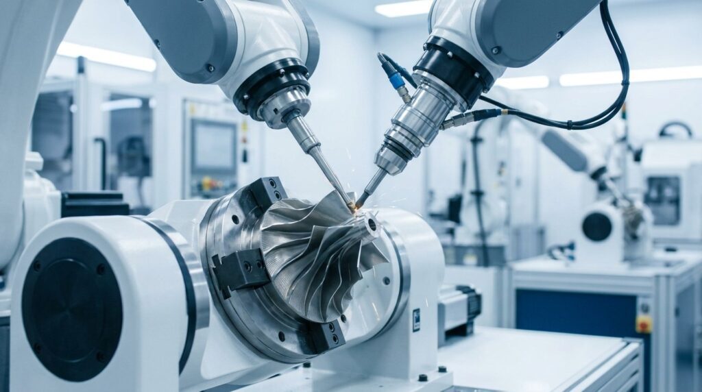
In aerospace manufacturing, turbine and compressor blades are among the most demanding components a finishing shop will ever see. As the core kinetic energy conversion components of jet engines and heavy-duty gas turbines, their surface quality directly influences the engine’s thrust-to-weight ratio, fuel efficiency, and flight safety. This article provides an in-depth analysis of the core challenge: deburring and precision polishing Titanium and Nickel-based Superalloy blades. We examine how automated robotic systems—equipped with active force control and Offline Programming (OLP) technologies—address the aerodynamic profile distortion and inconsistency risks of manual grinding, delivering stable micron-level precision.
What is an Aerospace Turbine Blade?
Aerospace turbine blades are installed in the compressor or turbine sections of jet engines. They operate under extreme physical environments: high-speed centrifugal forces of tens of thousands of RPMs, and gas temperatures that reach far beyond what most alloys can tolerate in the hot turbine section—where nickel-based superalloy blades dominate. In the cooler front compressor stages, titanium alloy blades are standard, and it is these titanium compressor blades, together with nickel-based turbine hardware, that set the agenda for finishing equipment.
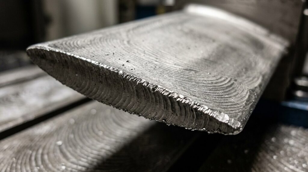
Turbine Blade Manufacturing Application Scenarios
Whether for commercial airliner engines (like the LEAP or Trent series) or heavy-duty gas turbines for power plants, these blades are typically manufactured from extremely difficult-to-machine Titanium alloys or Nickel-based superalloys (such as Inconel or Hastelloy) via precision investment casting or 5-axis CNC machining.
After primary machining, the blade surfaces are left with distinct microscopic tool marks. Furthermore, sharp flash and burrs are generated around the complex root/dovetail sections, as well as along the highly delicate Leading Edge (LE) and Trailing Edge (TE). If these surface defects are not removed through extremely precise polishing, they can cause stress concentrations and accelerate fatigue cracking, with potentially catastrophic consequences in flight.
Structural Characteristics For Turbine Blade
The geometric structure of turbine blades poses extreme challenges for surface treatment:
- Intensely Complex Aerodynamic Surfaces (Airfoil Profile): The pressure and suction sides of the blade are 3D free-form surfaces shaped by rigorous fluid-dynamics design. Even a minute alteration to their shape can trigger airflow separation and reduce engine efficiency.
- Micron-Thin Edges: The leading and trailing edges of the blade are razor-thin (sometimes measuring fractions of a millimeter). The slightest over-grinding will destroy the perfect “teardrop” cross-section.
- Difficult-to-Machine Materials (Superalloys): Titanium and superalloys combine high strength with extremely poor thermal conductivity. They are highly susceptible to thermal burning or surface hardening layers during grinding.
Key Characteristics of Turbine Blade Polishing
Caratteristiche principali:
- Absolute Profile Fidelity: The deburring and polishing process must never alter the original 3D dimensions created by the 5-axis CNC. Material removal must be strictly controlled at the micron level.
- Superb Surface Roughness: Typically required to achieve precision levels of Ra 0.2 – 0.4 μm to maximally reduce aerodynamic friction drag.
- Consistent Residual Compressive Stress: The polishing process must not only smooth the surface but avoid generating micro-cracks. It is often combined with shot peening to induce a beneficial compressive stress layer, enhancing fatigue resistance.
Technical Parameters for Blade Polishing
| Articolo | Intervallo dei parametri | Note |
| Burr & Tool Mark Removal | Fine Grit Ceramic/AlOx Belts | Requires specific coolant consumables for Titanium |
| Airfoil Precision Polish | Wool Wheel / Spec Non-woven | Used with aerospace compound to remove all micro-scratches |
| Controllo della forza di contatto | 2N – 15N (Ultra-High Freq) | “Feather-touch” blending, absolutely protects thin edges |
| Rugosità superficiale finale | Ra ≤ 0.4 μm | Finished to the OEM engine specification on the drawing |
| Contour Tolerance Control | ± 0.01 mm | Relies on 1000Hz micron-level force control & 3D vision |
Why Must Aerospace Blades Use Robotic Polishing?
The Fatal Flaws of Conventional Manual Grinding
In the past, polishing aerospace blades relied heavily on the “feel” of master craftsmen with decades of experience. However, given the ruthless demands for yield and capacity in modern aerospace manufacturing, manual grinding is no longer sustainable:
| Punto dolente | Problema specifico | Impatto |
| Steep “Over-Cut” Scrap Costs | Superalloy blades are high-value parts. Manual grinding easily cuts tens of microns too deep on the trailing edge. | Scrapping one blade can mean losing thousands of dollars, and manual yields are difficult to hold at a consistently high level. |
| Profile Consistency Disasters | An engine requires hundreds of blades. If polished by different workers, the actual aerodynamic profile of every blade varies slightly. | Leads to severe dynamic balancing issues during engine assembly, impacting overall thrust and fuel economy. |
| Thermal Burning & Metrological Changes | Titanium stores heat rapidly. Prolonged manual dwelling causes localized high heat, destroying fatigue properties. | Plants severe, hidden safety hazards for aviation flight. |
Vantaggi dell'automazione robotica
Introducing a robotic precision deburring system equipped with micron-level active force control is a practical route for the aerospace engine supply chain to achieve stable quality control and fully traceable delivery. If you are new to the underlying technology, our primer on what robotic deburring actually does is a good starting point:
| Dimensione di confronto | Rettifica manuale | Lucidatura robotizzata | Miglioramento |
| Profile Fidelity | High error, easily alters aero shape | Milligram-precise cutting, constant force | Consistent contour accuracy across the blade set |
| Scrap Rate Control | One slip of the hand causes a scrap | Smart yielding & anti-collision monitoring | Eliminates human over-cutting; scrap from grinding errors drops sharply |
| Data Traceability | No retained data | Logs force & coordinates of every cut | Process data supports AS9100 audit requirements |
| Efficienza di lavorazione | Slow, highly limited output | Multi-station high-speed collaboration | Substantially higher capacity for high-volume deliveries |
Vantaggi principali:
- Micron-Level Active Compliant Force Control: This is the anchor for aerospace blade machining and the core capability that separates force-controlled robotic polishing machines from position-only automation. The force control system monitors the contact force between the tool and the blade at 1000Hz. When the robot processes the razor-sharp and fragile trailing edge, it automatically drops the pressure to mere Newtons (N), brushing away micro-burrs without eating into the parent material—true “deburring without harming the profile.”
- Offline Programming (OLP) & Digital Twins: Blade surfaces are highly complex. Engineers directly import high-precision 3D CAD models, and the software automatically recognizes the aerodynamic surfaces, generating Normal Vector polishing paths that conform to the geometry. This avoids the deviations inherent in manual teaching, keeping every step of the robot’s motion tied to the CAD model.
Automated Turbine Blade Polishing Process Workflow
Questo processo utilizza 8 core steps to process a high-end Titanium compressor blade from a “burred blank” to a “high-precision surface.”
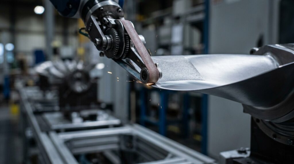
Aerospace Turbine Blade Robotic Polishing & Deburring Complete Process Flow
| Processo | Nome del processo | Attrezzatura | Consumabile | Tempo | Precisione / Scopo |
| 01 | Zero-Stress High-Prec. Clamp | Pneumatic Soft/Freeze Jig | - | 20s | Ensures repeat precision without inducing clamping distortion |
| 02 | Root Dovetail Deburring | Robot + mandrino ad alta velocità | Micro Carbide Burr | 45s | Precisely mills hard flash from the complex fir-tree root |
| 03 | Airfoil CNC Mark Blending | Robot + Compliant Belt Sander | Ultra-Fine AlOx Belt | 120s | Follows aero curves to erase micro-waves left by 5-axis milling |
| 04 | LE / TE Precision Blending | Robot + Micro Belt Sander | Custom Aero Abrasive | 90s | Uses feather-light force to preserve teardrop cross-sections |
| 05 | Airfoil Precision Polish | Robot + Wool Polishing Wheel | Aero-Grade Micro Paste | 150s | Elevates surface finish to Ra < 0.4μm, reducing aero drag |
| 06 | Cold MQL Cooling | MQL Spray System | Aero-Certified Coolant | Cont. | Strictly controls contact temp, preventing Titanium burns |
| 07 | Automated Ultrasonic Wash | Linea a ultrasuoni multi-serbatoio | Non-Destructive Solvent | 180s | Thoroughly strips abrasive and metal residue from pores |
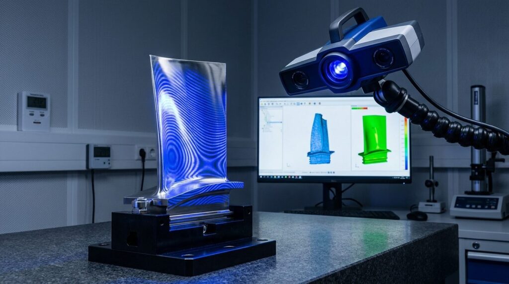
| 08 | 3D Blue Light Full Scan | Optical 3D Profile Scanner | - | 60s | Generates full 3D deviation color maps for inspection records |
Aerospace Turbine Blade Robotic Polishing & Deburring Process Descriptions
Step 1: Zero-Stress Clamping
Scopo: Stable gripping without introducing deformation.
Punti chiave: Because blades are extremely thin, traditional hard mechanical clamping causes the blade itself to bend. Typically, customized conformal polyurethane soft fixtures are used, or in the most extreme high-end applications, Freeze Gripping (using liquid nitrogen) is utilized to achieve absolute rigid fixation with zero stress.
Step 2: Root Dovetail Deburring
Scopo: Clean the complex “fir-tree” root used for mounting to the turbine disk.
Punti chiave: Leveraging the extreme 6-axis agility of the robot, it swaps to micro-tools to precisely dive into the complex gear-like grooves of the dovetail, clearing micro-flash without altering the critical assembly tolerances. Dovetail and fir-tree roots are among the most common geometries in industrial robotic deburring applications, and blade roots push the same tooling principles to their limit.
Step 3 & 4: Airfoil Blending & Edge Finishing
Scopo: The core challenge. Erase tool marks while preserving the aerodynamic shape.
Punti chiave: This is where active force control matters most. Guided by OLP paths, the belt sander stays perpendicular (normal) to the free-form surface. The contact force drops automatically from 15N on the belly of the blade to under 2N the instant it reaches the razor-thin trailing edge.
Step 5: Airfoil Precision Polishing
Scopo: Reduce surface roughness to enhance fatigue life.
Punti chiave: Switches to extremely soft wool wheels paired with specific polishing media. It softly strokes the surface along the direction of airflow, eliminating all potential microscopic stress concentration points.
Step 8: 3D Blue Light Full Scan
Scopo: Full 3D inspection of every blade.
Punti chiave: A high-precision blue light scanner captures millions of surface point cloud data points from the polished blade, comparing it against the original 3D CAD model. Any over-cut or under-cut exceeding 0.01mm will trigger a red alert on the deviation color map.
Sfide e soluzioni di lavorazione
Challenge 1: Superalloys are Supremely Difficult to Cut and Burn Instantly
Problema:
- Titanium and Nickel-based superalloys (like Inconel 718) are used in jet engines specifically because they maintain extreme strength and toughness at high temperatures.
- This means they are incredibly hard to grind. Traditional grinding easily causes abrasive belts to wear and dull instantly, generating massive friction heat that immediately burns the surface, causes oxidative discoloration, or even destroys the internal metallographic structure.
Soluzione:
- Cold Cutting Strategy + MQL Lubrication + Smart Wear Compensation.
- The system employs extremely low feed speeds with constant, light pressure. Throughout the process, a Minimum Quantity Lubrication (MQL) system precisely sprays fluid to instantly carry heat away from the cutting zone. Concurrently, the force control system senses consumable wear in real-time, automatically micro-adjusting the feed to ensure every cut remains in an optimal “cold cut” state.
- Risultato: The risk of thermal burning is effectively controlled, and metallographic and hardness testing of polished blade surfaces consistently confirms an undamaged structure.
Challenge 2: The Micron-Level Fragility of Leading/Trailing Edges
Problema:
- The trailing exhaust edge of a blade is often less than 0.5mm thick—incredibly sharp and fragile.
- When grinding this area, applying even a few Newtons too much force, or if the robot path deviates by a mere 0.05mm, can directly flatten or snap the trailing edge—turning a blade worth thousands of dollars into scrap metal.
Soluzione:
- Introduce High-Frequency Hybrid Force/Position Control Architecture.
- When machining edge zones, the robot does not rely solely on the precise coordinates (position) of offline programming; it grants highest-priority “takeover rights” to the force sensor. The moment the sensor detects a micro-spike in resistance (meaning it has contacted the fragile edge), the system automatically executes a “yielding” protective motion.
- Risultato: Reliable protection for ultra-thin edges. The ground leading and trailing edges maintain the design-mandated teardrop aerodynamic shapes, and over-cut scrap falls to a negligible level.
Application Scenario
Production Background
A typical deployment target for this type of cell is an aero-engine component supplier in Europe producing high-pressure compressor and turbine blades for commercial airliner engine programs. The finishing workshop is usually the bottleneck when blade output needs to scale up for a new engine generation.
Sfide tecniche
- Capacity expansion for a new generation of titanium alloy blades was being bottlenecked by the grinding workshop.
- Legacy manual grinding yields were unstable. Because titanium blades are high-value parts, scrap losses from manual over-cutting alone accumulated into a serious cost problem.
- The engine OEM required complete digital traceability of the manufacturing process for critical components, which traditional manual operations could not provide.
La soluzione
| Articolo | Configurazione |
| Pezzo in lavorazione | Aero-Engine Titanium High-Pressure Compressor Blade |
| Materiale | Ti-6Al-4V Titanium Alloy Forging |
| Attrezzatura | High-Rigidity 6-Axis Robot + Force Control Micro Sander + MQL |
| Core Tech | 1000Hz Active Compliant Force Control + Blue Light 3D Scan Check |
| Processo | OLP Path Gen -> Root Flash Mill -> Cold Force Blend -> Edge Micro-Finish |
| Tempo di ciclo | A few minutes for a comprehensive polish of a single complex blade |
Risultati dell'implementazione
- Scrap Containment: Active force control plays the decisive role here. With the system in place, the scrap rate for high-pressure blades due to dimensional grinding errors typically falls from double digits to a low single-digit level, containing what used to be a major annual scrap cost.
- Consistent Profiles: Aerodynamic profile errors across the production batch concentrate within a narrow tolerance band, which improves dynamic balance consistency during final engine assembly.
- Digital Traceability: The system logs the pressure curves, RPM, and 3D coordinates during the grinding of every blade, automatically generating a digital process dossier. This documented evidence supports the audit requirements of the AS9100 aerospace quality system.
FAQ
Q1: Can the robotic grinding system directly interface with our CMM (Coordinate Measuring Machine) data?
A: Yes. This is the core of closed-loop control in high-end aerospace manufacturing. Our system can ingest data from CMMs or 3D blue light scanners. If inspection reveals that the allowance left by the preceding CNC batch is abnormally large, the grinding software automatically parses this deviation data and dynamically generates an “adaptive” grinding toolpath for precise remedial compensation—closing the loop between inspection and production.
Q2: Given the extreme flammability and explosiveness of Titanium dust, how does the system prevent disasters?
A: The aerospace industry works to some of the strictest explosion-protection standards in manufacturing (ATEX/NFPA). Our aerospace-grade grinding cells are built accordingly: fully enclosed micro-negative pressure explosion-proof doors, a complete suite of Ex-rated motors and sensors, and a dedicated Water Wash titanium dust extraction system. The moment dust is generated, it is drawn into water and passivated, removing the conditions a titanium dust explosion requires.
Q3: How long does it take from writing a grinding program for a new blade to starting trial production?
A: Leveraging advanced Offline Programming (OLP) digital twin technology, you do not waste time teaching on the physical robot. Engineers import the blade’s 3D CAD and desired contact force parameters on a computer, and the software automatically generates collision-free paths. For an entirely new, complex blade, moving from programming to physical proof-of-concept polishing typically takes about one working day.
Q4: How is the Return on Investment (ROI) calculated when investing in an aerospace-grade robotic system of this caliber?
A: Calculating ROI in the aerospace sector is different from standard industries. You cannot simply calculate “how many workers’ wages were saved.” The core return lies in the scrap costs recovered. A single titanium blade can be worth thousands of dollars, so cutting the scrap rate by even a modest percentage—combined with the capacity increase—adds up quickly. Based on our servizi di valutazione dei progetti e di verifica della fattibilità, the payback period for these high-end systems is often shorter than buyers expect, with many projects recovering the investment within roughly a year.
Conclusione
The precision grinding and polishing of aerospace turbine blades represent one of the highest technical barriers in manufacturing. Adopting an automated robotic system integrating micron-level active force control and OLP offline path planning addresses the profile distortion, scrap losses, and thermal burning hazards caused by manual grinding. It navigates razor-thin leading/trailing edges and complex free-form surfaces under constant force, keeping every blade’s aerodynamic shape within specification. For aero-engine component suppliers, this is a practical route to easing capacity constraints, stabilizing yields, and building the traceability that aviation quality systems require.
If your manufacturing plant is battling low yields in superalloy blade grinding, heavy scrap losses from manual over-cutting, and strict dimensional consistency requirements, contact our aerospace automation expert team to obtain a dedicated micron-level grinding technical assessment and machine trial solution.